IES MASTER GATE MATERIAL
HYDRAULIC MACHINES
GATE – PSU – IES – GOVT EXAMS – STUDY MATERIAL
FREE DOWNLOAD PDF


CONTENTS
- HYDRO ELECTRIC PLANT
- DYNAMIC ACTION OF FLUID
- TURBINES
- PUMPS
BRIEF INTRODUCTION TO THIS BOOK :
Hydro Electric Plant
WHAT IS A HYDRO ELECTRIC POWER PLANT? EXPLAINED.
INTRODUCTION : The purpose of Hydro-Electric Plant is to harness power from water flowing.under pressure.
-
Water flowing under pressure has two forms of energy Kinetic and Potential.
-
These kinetic and potential energy possessed by water is converted into mechanical power by Hydraulic Turbine.
-
The hydraulic turbine is, thus, a prime mover which when coupled to a generator produces electric power.
-
Hydro-Electric Projects may not be used exclusively for power generation. Sometimes, they are the off- shoot of flood control and irrigation projects and are known as”Multipurpose-Projects”.
HEAD AND EFFICIENCIES OF TURBINES :
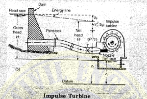
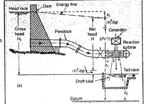
HEAD : Head is the difference in elevation between two levels of water. It can be characterized as
-
Gross Head and
-
Net or Effective head
(a) Gross Head is defined as the difference in elevation between the head race level at the intake and the tail race level at the discharge side, naturally, both the elevations have to be measured simultaneously. The gross head may vary as both the elevations of water do not remain the same.
(b) Net or Effective Head is the head obtained by subtracting all the losses from gross head in carrying water from the head race to the entrance of the turbine. These losses are due to friction occurring in tunnels, canals and a penstocks which lead the water into the turbine.
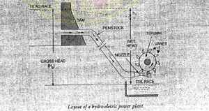
THE MAIN COMPONENTS OF HYDRO ELECTRIC POWER PLANT :
(i) Storage Reservoir : The storage reservoir may be natural or artificial.
Natural-Lakes, Mountains. Artificial-Dam constructed across river valley.
(ii) Waterways and their control works: Waterway is a passage through which water is carried from storage reservoir to the power house. It consists of tunnel, canal, flumes, forebays, penstocks etc.
Forebays
-
Forebay is an enlarged section of a canal spread out to accommodate the required width
-
It is provided with intake structure, to direct water into the penstocks.
-
Intake should be provided with trash racks so as to prevent the entry of debris into the penstock and thus avoid the possible damage to turbine runnes.
-
Its function is store temporarily the water rejected by the Plant when the electrical load is reduced and also to meet the instantaneous increased demand of water due to sudden increase in load.
Surge Tank :
-
It is a reservoir fitted at some opening made on along pipe line to receive the rejected flow when the pipeline is sud It also helps in absorbing the den pressure rise due to closing of valve when load on turbine is reduced thus eliminating water hammer effect.
-
When it is not possible to provide forestay we provide surge tank to absorb pressure fluctuation
-
It reduces the distance between the turbine and free surface.
Penstock :
-
It is a pressure pipe carrying water from the storage location to the turbine.
-
Long penstock should be provided with surge tank so that water hammer pressure could be dissipated.
(iii) Hydraulic Turbines : Turbines are machines which convert hydraulic energy into mechanical energy.
(iv) The Power House : A power house is a building consisting of a sub structure to support the hydraulic and electrical and a super structure to house and protect this equipment.
(v) The Draft Tube : It is a conduit which connects the outlet of a reaction turbine runner to the tailrace
(vi) The Tailrace : It is a waterway to conduct water discharged from turbine to a suitable point where it can be eafely disposed of or stored to be pumped back into original reservoir.
Dynamic Action of Fluid
WHAT IS THE DYNAMIC ACTION OF FLUID ?
INTRODUCTION :
-
A stream of fluid entering in a machine such as a hydraulic turbine, pump, has more or less a defined direction
-
A force is always required to act upon the fluid to change its velocity either in direction or in magnitude.
-
Newton’s third Law of motion states that to every action there is an equal and opposite reaction.
-
According to this law an equal and opposite force is exerted by the fluid upon the body that causes the change.
-
This force exerted by virtue of fluid motion is called, A Dynamic Force which always causes a change in velocity/change in momentum) and must be distinguished from hydrostatic pressure.
-
Turbines : Turbines are defined as hydraulic machine which convert hydraulic energy into mechanical energy, mechanical energy inturns is converted to electrical energy.
-
The idea of using water as a source of energy was first introduced in Asia(India and China)
-
Bernoulli first wrote a theory for conversion of water power into other forms of energy
-
In general, a water turbine consists of a wheel called runner(or rotor) having a number of specially designed vanes or blades or buckets.
-
The water possessing a large amount of hydraulic energy when strike the vanes, it does work and cause the runner to rotate.
-
The mechanical energy so developed is supplied to the generator coupled to the runner, which then generates electrical energy.
PELTON WHEEL TURBINE
-
Pelton wheel turbine is a tangential flow, high head impulse turbine.
-
In this turbine water jet impinges on the bucket attached to the shaft of turbine which causes force on bucket.
-
This force creates torque necessary for rotation of shaft.
-
All the head is converted to kinetic head before the jet impinges on the bucket.
-
While moving on the bucket, water is always in contact with atmosphere .
-
Hence throughout operation water is atmospheric pressure.
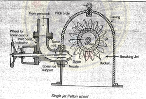
The Main Parts of Pelton Turbine are :
(i) Nozzle and flow regulating arrangement(spear or deflector)
(ii) Runner and buckets.
(iii) Casing.
(iv) Breaking Jet.
(i) Nozzle and Spear(or Deflector)
-
Nozzle Spear Arrangement : It is a guide mechanism which controls the water passing through the nozzle and striking the bucket. Thus it helps in meeting the variable demand of power.
-
It maintain the speed of the wheel constant even when head varies.
-
When speed of the wheel increases, the spear is pushed into the nozzle thereby reducing the quantity of water striking the bucket. If the speed of the wheel falls, the spear is withdrawn back allowing a greater quantity of water to pass through nozzle.
-
When water requirement of turbine falls, the quantity of water flowing through the nozzle has to be reduced. This may lead to pressure rise and the pipe carrying water may brust due to water hammer phenomenon. Thus a deflector or bypass nozzle is used to that when some water is not required by turbine, it is bypassed& not allowed to strike the runner.
(ii) Runner or Buckets :
-
Each bucket is divided into two parts by a splitter which has a sharp edge at the centre giving t shape of a double hemispherical cup.
-
The splitter divided the jet without shock, into two parts moving sideways in opposite direction.
-
The bucket are shaped in such a way that the jet. gets deflected through 160 to 170°, but normally adopted is value of deflection is 165 degrees
-
The main efficiency controlling dimension of the bucket its width B
-
If the B is too small, the water of jet is not deflected smoothly with the result that there is sufficient dissipation of energy due to turbulance in the bucket.
-
If B is too large, the surface over which the water glides become to more friction loss. Hence large giving rise the optimum value is adopted.
-
Advantage of symmetrical bucket is that due to symmetry net thrust in the direction perpendicular to the initial direction of velocity is zero. Thus, the shaft/bearing is not subjected to any lateral loads.
Suitable material for buckets :
-
Cast Iron for low head
-
Bronze(or stainless steel) for high head.
(iii) Casing : The casing of a Pelton turbine has no hydraulic function to perform. It is necessary only to prevent splashing and to lead the water to the tailrace and also safeguard against accidents
iv) Breaking Jet : Purpose it to stop the runner in shortest possible time for which jet is impinges on the backside of the bucket.


![[GATE - PSU - GOVT EXAMS] STEEL STRUCTURES IES MASTERS Study Material Main Page 1](https://civilenggforall.com/wp-content/uploads/2017/07/GATE-PSU-GOVT-EXAMS-STEEL-STRUCTURES-IES-MASTERS-Study-Material-Main-Page-1-400x300.jpeg)