
CONTENTS
- Analysis of Concrete Structures
- Working Stress Method
- Ultimate Load Method
- Whitney’s Theory
- Limit State Design
- Characteristic Strength
- Assumptions in the Limit State Design
- Recommendations of Indian Standard Codes
- Limit State of Collapse-Flexure
- Modes of Failure in Flexure
- Limiting Values of Moment of Resistance
- Limit State of Serviceability
- Design of Beams
- Effective Depth
- Design of Doubly Reinforced Beams
- Design of Compression Members
- Short Column Under Axial Compression
- Reinforcement
- Column
- Column Footings
- Depth from B.M. Consideration
- Depth from Punching Shear Consideration
- Check for Diagonal Tension
- Prestressing
- Fully Prestressed Section
- Deflection of Prestressed Concrete Member
- Introduction to IS: 456: 2000

There are three design philosophies related to reinforced and prestressed concrete:
- Working stress method
- Ultimate load method
- Limit state method
WORKING STRESS METHOD
Assumptions of Working Stress Method
- A section which is plane before bending remains plane after bending.
- Bond between steel and concrete is perfect within the elastic limit of steel.
- (iii)Tensile strength of concrete can be ignored.
- Concrete is elastic, i.e. stress in concrete varies linearly from zero at the neutral axis to maximum at the extreme fibre.
- Modular ratio has the value 280/3σcbc , where σcbc is permissible compressive stress in bending in N/mm2
According to Indian Standard IS:456, 2000, permissible compressive stress in bending in concrete is one-third of 28-day cube strength of concrete. The corresponding factor of safety is 1.78 for steel, which is applied on the yield strength of steel in tension.
Drawbacks of the Working Stress Method
- Concrete is not elastic, and stress distribution in the concrete section is not triangular.
- Factor of safety is applied on the stresses, and different degrees of uncertainties associated with different types of loads is not accounted for.
- It is difficult to account for shrinkage and creep by calculation of elastic stresses.
IES MASTER CIVIL ENGINEERING GATE STUDY MATERIALS PDF: CLICK HERE
ULTIMATE LOAD METHOD
In this method, working loads are increased by suitable factors, called load factors, to obtain ultimate loads and structure is designed to resist these loads.
Whitney’s Theory
It is based on the assumption that, ultimate strain in concrete is 0.3 per cent and compressive stress at the extreme edge corresponds to this strain. Whitney replaced actual parabolic stress diagram by a rectangular stress diagram such that centre of gravity of both diagrams lies at the same point and their areas are also equal.
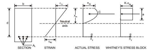
where, α = depth of rectangular stress block = 0.573d according to Whitney = 0.43d according to IS: 456-1964
xm = depth of neutral axis
z = level arm
σcu = ultimate 28-day cylinder strength of concrete
Kσcu = average stress = 0.85σcu according to Whitney = 0.55σcu according to IS:456– 1964
σy = yield stress in steel
Ԑcu = ultimate strain in concrete
Ԑsy = yield strain in steel
Assumptions Based on IS: 456– 1964
- A section which is plane before bending remains plane after bending.
- At ultimate strength stresses and strains are not proportional and distribution of compressive stresses is non-linear in a section subjected to bending. The stress block may be assumed as a rectangle, parabola or any other shape, which gives ultimate strength in reasonable agreement with test results.
- Maximum fibre strength in concrete does not exceed 0.68σcu. As in Whitney’s theory, a rectangular stress block with a = 0.43d and the average stress = 0.55σcu can be assumed for analysis.
- Tensile strength of concrete is ignored.
Indian Standard, IS: 456– 1964 stipulated following conditions for ultimate design load, u
- For structures in which the effects of wind and earthquake loads can be ignored, U should be equal to 1.5 D + 2.2 L
- For structures in which earthquake loads should be considered, U should be equal to (1.5 D + 2.2 L + 0.5 W) or (1.5 D + 0.5 L + 2.2 W) whichever gives the critical condition. where, D is dead load, L is live load, and W is wind or earthquake load. coefficients of D, L and W represent load factor.
Drawbacks
- Since load factor is applied on the working loads, there is no provision to account for the uncertainties associated with variations in material stresses.
- There is no provision in the method for control against excessive deflections.
ACE ACADEMY CIVIL ENGINEERING GATE STUDY MATERIALS PDF: CLICK HERE
LIMIT STATE DESIGN
The object of limit state design is to achieve an acceptable probability that a structure will not become unserviceable in its lifetime. The condition of a structure when it becomes unserviceable is called limit state. Most important of these limit states which must be examined in design are:
- Ultimate limit state: Neither the whole structure nor any part of the structure should collapse under foreseeable overload,
- Serviceability limit state of deflection: Deflection of the structure should not adversely affect the appearance of the structure,
- Serviceability limit state of cracking: Cracking of the concrete should not affect the appearance or durability of the concrete,
- Serviceability limit state of vibration: Vibration should not be such as to cause alarm of discomfort to the user.
Therefore, collapse limit state at which the strength must be adequate to carry the loads with due consideration to stability, and serviceability limit state at which the deflection cracking and vibration must not be excessive.
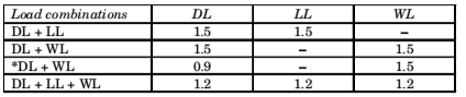
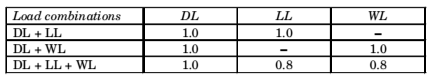
Partial Factor of Safety for Limit State of Collapse
Considered when stability against overturning or stress reversal is critical Where DL = Dead load, WL = Wind load, LL = Live Load
MADE EASY CIVIL ENGINEERING GATE NOTES PDF: CLICK HERE
Assumptions in the Limit State Design
- Plane sections normal to the axis of the member remain plane after bending. i.e., strain at any point on the cross-section is directly proportional to the distance from the neutral axis.
- Maximum strain in concrete at the outermost compression fibre is 0.0035.
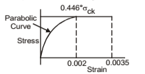
- Design stress-strain relationship for concrete is as shown in the Figure
- Tensile strength of concrete can be ignored.
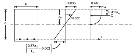
- Maximum compressive stress in concrete is equal to 0.67 σck
- Strain in the tension reinforcement is to be not less than 0.87σy/Es + 0.002
This assumption is intended to ensure ductile failure i.e. tensile reinforcement has to undergo a certain degree of inelastic deformation before the concrete fails in compression.
Recommendations of Indian Standard Codes
Grades of Concrete – Following six grades of concrete can be used for reinforced concrete work: M15, M20, M25, M30, M35 and M40. The number in the grade designation refers to the characteristic strength σck of 15 cm cubes at 28 days, expressed in N/mm2. Generally, grades M15 and M20 are used for flexural members. Grade M35 and M40 are used for prestressed beam.
Reinforcement Bars – For design purposes, characteristic strength of steel is taken as 250 or 415 N/mm2, as the case may be.
ACE ACADEMY CIVIL ENGINEERING GATE HANDWRITTEN NOTES PDF: CLICK HERE
Stress-Strain Relationship for Concrete
Codes permits the use of stress-strain curve as shown in the figure. Compressive strength of concrete is assumed as 0.67σck. With a value of 1.5 for the partial safety factor for material strength, maximum compressive stress in concrete for design purpose is 0.44σck.
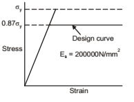
The design yield stress works out, with an assumed value of 1.15 for steel, to 0.87 σy. Stress-strain relationship for steel in tension and compression can be assumed to be the same. For mild steel, stress-strain curve, for design purposes, will be as shown in the figure. For cold worked bars, the stress is proportional to strain up to a stress equal to 0.87 σy
Modes of Failure in Flexure
If ratio of steel to concrete in a beam is such that maximum strain in the two materials reach simultaneously, a sudden failure would occur with less alarming deflection. Such a beam is called balanced reinforced beam. When amount of steel is kept less than that in the balanced section, then neutral axis moves upward to satisfy equilibrium condition that the force of compression is equal to force of tension. In this process, centre of gravity of compressive force shifts upward. Under increasing bending moment, steel is strained beyond the yield point and maximum strain in concrete remains less than 0.35 percent.
If beam is further loaded, then strain in the section increases. Once the steel has yielded, it does not take any additional stress for the additional strain and total force of tension remains constant. However, compressive stresses in concrete do increase with the additional strains. Thus, neutral axis and centre of gravity of compressive forces further shift upward to maintain equilibrium. This process of shift in neutral axis continues until maximum strain in concrete reaches its ultimate value, i.e. 0.35 percent, and concrete is crushed. Such a beam is called under-reinforced beam. The failure is called tension failure because yielding of steel was responsible for continued higher strains in concrete, resulting in its failure.
When amount of steel is kept more than that in the balanced condition, then neutral axis tends to move downward and strain in steel remains in the elastic region. If beam is further loaded, then stress and strain in steel keep on increasing and so is the force in tension. The additional increase in the concrete stress is much slower. Thus, to maintain equilibrium of tension and compression forces, area of concrete resisting compression has to increase. In this process, neutral axis shifts further downward until maximum strain in concrete reaches its ultimate value i.e., 0.35 percent and concrete is crushed. The steel is still well within the elastic limit. Such a beam is called over-reinforced beam and the failure, is called compression failure. A compression failure is a brittle failure and is to be avoided. The maximum depth of neutral axis in a design is, therefore, to be limited. Hence stipulation in the code that, maximum strain in tension reinforcement in the section at failure should not be less than σy/1.15Es + 0.002
CONCRETE STRUCTURES (RCC) CIVIL ENGINEERING GATE 2020 STUDY MATERIAL FREE DOWNLOAD PDF
DOWNLOAD LINK : CLICK HERE
PASSWORD : CivilEnggForAll
OTHER USEFUL BOOKS
- CIVIL ENGINEERING TEXTBOOKS WITH DOWNLOAD LINKS
- IES MASTER CIVIL ENGINEERING GATE STUDY MATERIALS PDF
- ACE ACADEMY CIVIL ENGINEERING GATE STUDY MATERIALS PDF
- RAJASTHAN STAFF SELECTION BOARD (RSSB) JUNIOR ENGINEER DIPLOMA CIVIL ENGINEERING EXAM 2022 – HINDI & ENGLISH MEDIUM SOLVED PAPER – FREE DOWNLOAD PDF (CivilEnggForAll.com)
- ISRO TECHNICAL ASSISTANT EXAM 2022 – CIVIL ENGINEERING – HINDI & ENGLISH MEDIUM – SOLVED PAPER – FREE DOWNLOAD PDF (CivilEnggForAll.com)
- MADHYA PRADESH PUBLIC SERVICE (MPPSC) COMMISSION – ASSISTANT ENGINEER EXAM – MPPSC AE 2021 CIVIL ENGINEERING – SOLVED PAPER WITH EXPLANATIONS – PDF FREE DOWNLOAD
- BIHAR PUBLIC SERVICE COMMISSION (BPSC) ASSISTANT ENGINEER EXAM – 2022 – CIVIL ENGINEERING – SOLVED PAPER – FREE DOWNLOAD PDF (CivilEnggForAll.com)
- ODISHA PUBLIC SERVICE COMMISSION – OPSC AEE PANCHAYATI RAJ EXAM 2021 – SOLVED PAPER WITH EXPLANATION – FREE DOWNLOAD PDF