
CONTENTS
- STRESS
- STRAIN
- ELASTIC LIMIT
- NORMAL STRAIN
- SHEAR STRESS
- SHEAR STRAIN
- GAUGE LENGTH
- MODULUS OF ELASTICITY
- MODULUS OF RIGIDITY
- BULK MODULUS
- PROOF STRESS
- FACTOR OF SAFETY
- FREE BODY DIAGRAM
- STRESS-STRAIN DIAGRAM
- BRITTLE MATERIALS
- PROOF RESILIENCE
- MODULUS OF RESILIENCE
- BENDING MOMENTS AND SHEAR FORCE DIAGRAM
- SHEARING FORCE
- BENDING MOMENT
- CANTILEVERS
- CONTINUOUS BEAMS
- FIXED BEAMS
- MOMENT OF INERTIA
- PARALLEL AND PERPENDICULAR AXIS THEOREMS
- TRUSS ANALYSIS
- STRAIN ENERGY

STRESS
When some external forces are applied to a body, then the body offers internal resistance to these forces. The magnitude of the internal resisting force is numerically equal to the applied forces. These internal resisting force per unit area is called “stress”.
STRENGTH OF MATERIALS IES MASTER GATE STUDY MATERIAL : CLICK HERE
STRAIN
It is defined as change in length per unit length. The strain may be tensile or compressive depending upon whether the length increases (under tensile load) or decreases (under compressive load). It is a dimensionless quantity.
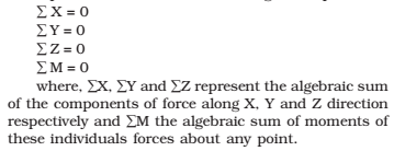
EQUATIONS OF STATIC EQUILIBRIUM
Whenever a solid body under the action of various forces is in static equilibrium or in the state of rest then the algebraic sum of the components of these forces along any chosen three perpendicular axes reference are separately zero. In addition, the algebraic sum of the moments of these forces about any point is also zero. It is not rotating. Mathematically, these results are expressed in the form of following four equations:
UNITS OF STRESS AND STRAIN:
Stress: The stress is defined as the internal force which is resisting to the applied force of deformation per unit area. Therefore, the stress is usually measured in Newtons/Metre Square (N/m2). It is also called Pascal (Pa). Since Pascal is a very small unit, it is not uncommon to use Mega Pascal (MPa) or Giga Pascal (GPa) as unit of stress, where 1 MPa = 106 Pa and 1 GPa = 109 Pa.
Strain: It is defined as the change in length (or elongation in length) per unit length. Mathematically it is defined as strain = change in length/unit length = l/L
ELASTIC LIMIT
Considering a tension test of a specimen of round section being stretched in a UTM. The load recorded by the universal testing machine is the reaction of the test specimen. At room temperature, the load extension diagram in general, at strain rate less than 2 × 10⁻³/sec will tend to follow the curve of the adjacent in the below figure. Which is typical for an annealed metal like aluminium or copper.
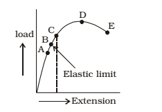
Initially, the relation between the load and extension is essentially linear–that is, portion OA of the curve, where A defines the limit of proportionality. On further straining the relation between load and extension linear–that is portion OA of the curve, where A defines the limit of proportionality. On further straining, the relation between the load and extension no longer remains linear but the material is still elastic. That is if the load is released the specimen will revert back to its original length. The maximum load which can be applied without causing permanent deformation is known as ‘‘Elastic Limit’’ represented by point B in the Fig-I attached. Usually the points A and B are very near to each other and the real difference can be achieved only by using highly sensitive measuring device. At the point B ends the elastic straining and the inelastic or plastic deformation ensues. Beyond the point B there is a general permanent extension of the test piece until the load attains a maximum value, point D.
STRENGTH OF MATERIALS ACE GATE STUDY MATERIAL PDF : CLICK HERE
FREE BODY DIAGRAM
The free body diagram of an element of a member in equilibrium is the diagram of only that member or element, as if made from the rest, with all the internal and external force.
STRENGTH OF MATERIALS STUDY MATERIAL FOR RRB JE PDF CIVILENGGFORALL
DOWNLOAD LINK : CLICK HERE
PASSWORD : CivilEnggForAll
OTHER USEFUL BOOKS
- RAJASTHAN STAFF SELECTION BOARD (RSSB) JUNIOR ENGINEER DIPLOMA CIVIL ENGINEERING EXAM 2022 – HINDI & ENGLISH MEDIUM SOLVED PAPER – FREE DOWNLOAD PDF (CivilEnggForAll.com)
- ISRO TECHNICAL ASSISTANT EXAM 2022 – CIVIL ENGINEERING – HINDI & ENGLISH MEDIUM – SOLVED PAPER – FREE DOWNLOAD PDF (CivilEnggForAll.com)
- MADHYA PRADESH PUBLIC SERVICE (MPPSC) COMMISSION – ASSISTANT ENGINEER EXAM – MPPSC AE 2021 CIVIL ENGINEERING – SOLVED PAPER WITH EXPLANATIONS – PDF FREE DOWNLOAD
- BIHAR PUBLIC SERVICE COMMISSION (BPSC) ASSISTANT ENGINEER EXAM – 2022 – CIVIL ENGINEERING – SOLVED PAPER – FREE DOWNLOAD PDF (CivilEnggForAll.com)
- ODISHA PUBLIC SERVICE COMMISSION – OPSC AEE PANCHAYATI RAJ EXAM 2021 – SOLVED PAPER WITH EXPLANATION – FREE DOWNLOAD PDF