
CONTENTS
- Structures
- Classification of Structures Based on Their Shapes
- Classification of Structures Based on Determinacy
- Degree of Redundancy
- Analysis of Structures
- Force Displacement Relationships
- Moment Distribution Method
- Carry Over Factor (C.O.F)
- Strain Energy Method
- Principle of Superposition
- Analysis of Trusses
- Analysis of Arches
- Influence Lines
- Matrix Method
- Stiffness of Members
- Nodal Degree of Freedom

STRUCTURES
A structure is an assemblage of number of components like slabs, beams, columns and foundations, which remain in equilibrium.
Classification of Structures
Based on Their Shapes Structural members and system which play the role of receiving their service loads at certain points and transmit them safely to certain other point, may be classified in a many of way. A broad classification based on their shapes are to divide the common civil engineering structure in to two type.
Skeletal Structures
This type of structure is looks like a skeleton. The member of a skeletal structure are connected to each other at joints or nodes. Depending upon the type of its joints, a skeletal structure may be classified in to either
- pin-jointed structure: Riveted & bolted joints in steel structure are treated as pint-jointed structure.
- rigid-jointed structure: The reinforced concrete framed structure are treated as rigid-jointed structure.
Skeletal structures may also be classified into either
- Two dimensional or Plane structure: A structure having all its member in one plane is called plane structure/frame.
- Three dimensional or space structure: A structure having members in three dimensions is called space structures/frame.
Steel Trusses, lattice girders and transmission towers are example of skeletal structures which are analysed as pin-jointed structure. Reinforced concrete building frames, rigid frames and bents, bow string girders and open spandrel arches are example of rigid-jointed skeletal structure.
STRUCTURAL ANALYSIS IES MASTER GATE STUDY MATERIAL PDF: CLICK HERE
Degree of Redundancy
In order to determine number of redundants, it is necessary to cut sufficient supports and structural members so that all loads are carried by simple beam and cantilever action. Then number of redundants is equal to the numbers of forces and moments required to restore continuity.
Static Indeterminacy
It refers to the number of redundant forces that are to be released to transform a structure into stable and statically determinate system. The additional equations required to solve statically indeterminate structures from prescribed conditions of translations and rotations, are called condition of compatibility. There are two types of indeterminacies:
- 2D truss: ns = m + r – 2j for Pin – jointed plane structure
- 3D truss: ns = m + r – 3j for Pin – jointed space structure
- 2D beam and frames: ns = 3(m – j) + r – t for rigid – jointed plane structure
- 3D beams and frames: ns = 6(m – j) + r – t for rigid – jointed space structure
where, ns = degree of statical indeterminacy, m = number of members, j = number of joints including support, r = number of reactions, t = number of releases like hinges = mr – 1, mr = number of element meeting at that hinge
Kinetic Indeterminacy
It refers to the number of independent components of joint displacements with respect to the specified set of axes. These displacements at the nodal points completely describe the response of the structure to any loading condition. The structure can be made kinematically determinate if all the joint displacements are restrained. The degree of kinematic indeterminacy may be defined as the number of unrestrained components of joint displacements.
- Any joint in space will have six independent components of displacements called degrees of freedom: three translations and three rotations.
- A joint in a plane frame will have three degrees of freedom: two translations and one rotation.
Degree of Kinematic indeterminacy
It can be defined as the number of unrestrained components of joint displacements.
Kinematic Indeterminacy Ik = NJ – C
where, N = number of degrees of freedom, J = number of joints, C = number of restraints against displacement giving rise to reaction components.
Method of Analysis
Two common method of matrix analysis are
- Flexibility method
- Stiffness or displacement method
Basic requirements to be satisfied
- Equilibrium between internal stress and external loads
- Compatibility of displacement at the joints
- Satisfaction of boundary conditions
STRUCTURAL ANALYSIS ACE ACADEMY GATE STUDY MATERIAL PDF: CLICK HERE
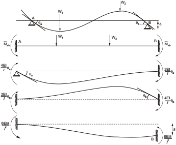
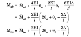
SLOPE DEFLECTION METHOD
This method can be used to analyse statically indeterminate beams and frames with rigid joints.
Sign Convention
- At the end of any span, clockwise end moments and clockwise slopes are positive.
- Downward deflection of the right end of a span with respect to its left end is positive.
- Deflection of the upper end towards the right relative to the lower end is positive. L
Let AB be any intermediate span of a continuous beam subjected to an external load system. Let θa and θb be the slopes at the ends A and B. Δ be the transverse downwards deflection of the right end B with respect to the left end A, and Mab and Mba be the final end moments at A and B respectively,
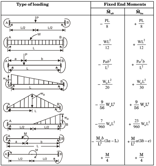
Fixed End Moments (FEM)
Fixed end moments for a transversely loaded member are the end moments developed when ends are fixed against rotation and translation. They may be determined by any of the standard methods of indeterminate analysis. Fixed end moments for a number of common loading cases are summarised in table for ready reference. Fixed end moments are expressed in accordance with the adopted sign convention.
Sign convention: Clockwise moment are positive, Anti-clockwise moments are negative.
STRUCTURAL ANALYSIS MADE EASY GATE NOTES PDF: CLICK HERE
PRINCIPLE OF SUPERPOSITION
An extremely useful principle in the analysis of linearly elastic structures is that of superposition. The principle states that if the displacements at all points in an elastic body are proportional to the forces producing them that is the body is linearly elastic, the effect (i.e. stresses and displacements) on such a body of a number of forces acting simultaneously is the sum of the effects of the forces applied separately. This principle can sometimes simplify the construction of shear force and bending moment diagrams.
ANALYSIS OF TRUSSES
Types of Trusses – Generally the form selected for a truss depends upon the purpose for which it is required. The Pratt, Howe, Warren and K trusses would, for example, be used to support bridge decks and large-span roofing systems (the Howe truss is no longer used. The Fink truss is used to support gable-ended roofs. The Bowstring truss is somewhat of a special case in that if the upper chord members are arranged such that the joints lie on a parabola and the loads, all of equal magnitude, are applied at the upper joints, the internal members carry no load. This result derives from arch theory but is rarely of practical significance since, generally, the loads would be applied to the lower chord joints as in the case of the truss being used to support a bridge deck. Frequently, plane trusses are connected together to form a three-dimensional structure. For example, in the overhead crane, the tower would usually comprise four plane trusses joined together to form a ‘box’ while the jibs would be constructed by connecting three plane trusses together to form a triangular cross-section.
Assumptions in Truss Analysis
The trusses consist of a series of triangular units. The triangle, even when its members are connected together by hinges or pins, is an inherently stable structure, i.e. it will not collapse under any arrangement of loads applied in its own plane. On the other hand, the rectangular structure would be unstable i f vertical loads were applied at the joints and would collapse under the loading system shown; in other words it is a mechanism. Further properties of a pin-jointed triangular structure are that the forces in the members are purely axial and that it is statically determinate so long as the structure is loaded and supported at the joints. Thus the forces in the members can be found using the equations of statical equilibrium. It follows that a truss comprising pin-jointed triangular units is also statically determinate if the above loading and support conditions are satisfied. We shall derive a simple test for determining whether or not a pin-jointed t r uss is statically determinate; this test, although applicable in most cases is not, as we shall see, foolproof. The assumptions on which the analysis of trusses is based are as follows:
- The members of the truss are connected at their ends by frictionless pins or
- The truss is loaded and supported only at its joints.
- The forces in the members of the truss are purely axial.
Method of Joints
The axial forces in the members of a simple pin-jointed triangular structure may be found by examining the equilibrium of their connecting pins or hinges in two directions at right angles. This approach may be extended to plane trusses to determine the axial forces in all their members; the method is known as the method of joint.
Method of Sections
In many trusses the maximum member forces, particularly in horizontal members, will occur in the central region where the applied bending moment would possibly have its maximum value. The calculation of member forces in the central region of a multibay truss such as the Pratt truss would be extremely tedious since the calculation must begin at an outside support and then proceed inwards joint by joint. This approach may be circumvented by using the method of sections.
The method is based on the premise that if a structure is in equilibrium, any portion or component of the structure will also be in equilibrium under the action of any external forces and the internal forces acting between the portion or component and the remainder of the structure.
STRUCTURAL ANALYSIS CIVIL ENGINEERING GATE 2020 STUDY MATERIAL FREE DOWNLOAD PDF
DOWNLOAD LINK : CLICK HERE
PASSWORD : CivilEnggForAll
OTHER USEFUL BOOKS
- CIVIL ENGINEERING TEXTBOOKS WITH DOWNLOAD LINKS
- IES MASTER CIVIL ENGINEERING GATE STUDY MATERIALS PDF
- ACE ACADEMY CIVIL ENGINEERING GATE STUDY MATERIALS PDF
- RAJASTHAN STAFF SELECTION BOARD (RSSB) JUNIOR ENGINEER DIPLOMA CIVIL ENGINEERING EXAM 2022 – HINDI & ENGLISH MEDIUM SOLVED PAPER – FREE DOWNLOAD PDF (CivilEnggForAll.com)
- ISRO TECHNICAL ASSISTANT EXAM 2022 – CIVIL ENGINEERING – HINDI & ENGLISH MEDIUM – SOLVED PAPER – FREE DOWNLOAD PDF (CivilEnggForAll.com)
- MADHYA PRADESH PUBLIC SERVICE (MPPSC) COMMISSION – ASSISTANT ENGINEER EXAM – MPPSC AE 2021 CIVIL ENGINEERING – SOLVED PAPER WITH EXPLANATIONS – PDF FREE DOWNLOAD
- BIHAR PUBLIC SERVICE COMMISSION (BPSC) ASSISTANT ENGINEER EXAM – 2022 – CIVIL ENGINEERING – SOLVED PAPER – FREE DOWNLOAD PDF (CivilEnggForAll.com)
- ODISHA PUBLIC SERVICE COMMISSION – OPSC AEE PANCHAYATI RAJ EXAM 2021 – SOLVED PAPER WITH EXPLANATION – FREE DOWNLOAD PDF