
CONTENTS
- FLUIDS
- PROPERTIES OF FLUIDS
- HYDROSTATICS
- MEASUREMENTS OF FLOW
- BERNOULLI’S THEOREM
- FLOW THROUGH PIPES
- FLOW IN OPEN CHANNELS
- FLUMES
- SPILLWAYS
- PUMPS
- CENTRIFUGAL PUMPS
- RECIPROCATING PUMPS
- TURBINES
- CLASSIFICATION OF HYDRAULIC TURBINES
- PELTON WHEEL
- FRANCIS TURBINE
FLUMES
A flume is a human-made channel for water in the form of an open declined gravity chute whose walls are raised above the surrounding terrain, in contrast to a trench or ditch, Flumes are not to be confused with aqueducts, which are built to transport water, rather than transporting materials using flowing water. Flumes route water from a diversion dam or weir to a desired material collection location. Flumes can accelerate slow, sub-critical (fr <1) flow to a supercritical state (Fr >1) by
- Change in elevation
- Contraction of the sidewalls, or
- Combination of the above two.
Accelerating slow flow to a supercritical state creates upstream conditions where under free flow conditions, the flow rate can be determined by measuring the water level at a single defined point in the flume (Ha).
The relationship between the water level at the point of measurement (Ha) and the flow rate can be obtained by test data (short-throated flumes) or derived formula (long-throated flumes).
HYDRAULIC MACHINES IES MASTER GATE STUDY MATERIAL PDF : CLICK HERE
Flume advantages:
- The ability to measure higher flow rates than a comparably sized weir.
- Less head loss (generally 1/4 th that of a weir).
- The ability to pass debris more rapidly.
- Wide range of styles and sizes.
- Off the shelf availability.
- Smaller installation footprint.
- Less rigorous maintenance requirements.
SPILLWAYS
Passages constructed either within a dam or in the periphery of the reservoir to safely pass the excess of the river water during flood are called spillways.
Ordinarily, the excess water is drawn from the top of the reservoir created by the dam and conveyed through an artificially created waterway back to the river. In some cases the water may be diverted to an adjacent river valley. In addition to providing sufficient capacity, the spillway must be hydraulically adequate and structurally safe and must be located in such a way that the out-falling discharges back into the river do not erode or undermine the downstream toe of the dam. The surface of spillway should also be such that it is able to withstand erosions or scouring due to the very high water velocities generated during the passage of a flood through the spillway.
Usually, spillways are provided with gates, which provides a better control on the discharge passing through. However in remote areas, where access to the gates by people may not be possible during all times as during the rainy season or in the night ungated spillways may have to be provided.
The capacity of spillway is usually worked out on the basic of a flood routing study. As such that the capacity of a spillway is seen to depend upon the following major factors:
- The inflow flood
- The volume of storage provided by the reservoir.
- Crest height of the spillway.
- Gated or ungated.
According to the Bureau of Indian standards guidelines IS: 11223 -1985 “Guidelines for fixing spillway capacity”, the following values of inflow design floods (IDF) should be looked into for the design of spillway.
- For large dams (defined as those with gross storage capacity greater than 60 million m3 or hydraulic head greater than 60 million m3 or hydraulic head between (2m and 30m),IDF should be based on the Standard Projects flood (SPF).
- For intermediate dams those with gross storage between 10 and 60 million m3 or hydraulic head between (2m and 30m), IDF should be based on the standard project flood(SPF).
- For small dams (gross storage between 0.5 to 10 million m3 or hydraulic head between 7.5m to 12m), IDM may be taken as the 100 year return period flood.
Spillways are ordinarily classified according to their most prominent feature, either as it pertains to the control, to the discharge channel, or to some other component. The common types of spillway in use are the following
- Free overfall (straight Drop) Spillway
- Overflow (ogee) Spillway
- Chute (Open Channel/Trough) Spillway.
- Side channel spillway.
- Soft (Drop Inlet/Morning Glory) Spillway
- Tunnel (Conduit) Spillway
- Siphon Spillway
FLUID MECHANICS ACE GATE STUDY MATERIAL PDF : CLICK HERE
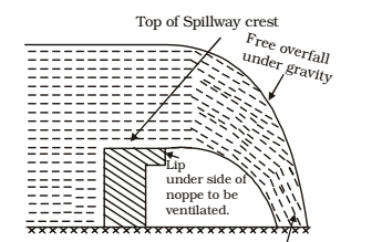
Free Overfall (Straight Drop) Spillway
This is the simplest type of spillway and may be constructed on small bunds or on thin arch dams etc. It is a low weir and simple vertical type fall structure
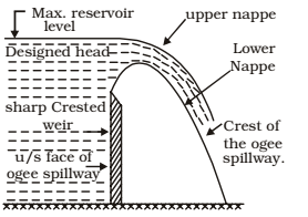
Ogee Spillway or Overflow Spillway
Ogee spillway is an improvement upon the free overfall spillway. It is widely used with concrete masonry, arch and buttress dams. such a spillway can be easily used on valleys where the width of the river is sufficient to provide the required crest length and the river bed below can be protected from scour at moderate costs.
Chute Spillway
An ogee spillway is mostly suitable for concrete gravity dams especially when the spillway is located within the dams body in the same valley. But for earthen and rockfill dams, a separate spillway is generally constructed in a blank or a saddle away from the main valley. The trough spillway or chute spillway is the simplest type of spillway which can be easily provided independently and at low costs.
Side channel spillway
A side channel spillway is one in which the control weir is placed approximately parallel to the upper portion of the discharge channel. The flow over the crest falls into a narrow trough opposite to the weir turns an approximate right angle and then continues into the main discharge channel. Discharge characteristics of a side channel spillway are similar to those of an ordinary overflow spillway and are dependent on the selected profile of the weir crest. Although the side channel is not hydraulically efficient, nor inexpensive, it has advantages which make it adoptable to spillway where a long overflow crest is required in order to limit the effect (surcharge held to cause flow) and the abutments are steep and precipitous.
HYDRAULIC MACHINERY MADE EASY GATE NOTES : CLICK HERE
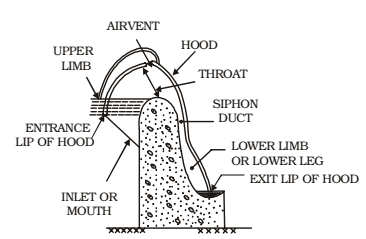
Siphon Spillway
A siphon spillway is a closed conduit system formed in the shape of an inverted U, positioned so that the inside of the bend of the upper passageway is at normal reservoir storage level. This type of siphon is also called a saddle siphon spillway. The initial discharges of the spillway as the reservoir level rises above normal, are similar to flow over weir, Siphonic action takes place after the air in the bend over the crest has been exhausted. Continuous flow is maintained by the suction effect due to the gravity pull of the water in the lower leg of the siphon.
Siphon spillway comprise usually of five components, which include an inlet, an upper leg, a throat or control section lower leg and an outlet. A siphon breaker air vent is also provided to control the siphonic action of the spillway so that it will cease operation when the reservoir water surface is drawn to the normal level. Otherwise the siphon would continue to operate until air entered the inlet. The inlet is generally placed well below the full Reservoir level to prevent entrance of drifting materials and to avoid the formation of vortices and drawdowns which might break siphonic action
PUMPS
The hydraulic machines which converts the mechanical energy into hydraulic energy are called pumps. The hydraulic energy is in the form of pressure energy. If the mechanical energy is converted into pressure energy by means of centrifugal force acting on the fluid, the hydraulic machine is called centrifugal pump.
CENTRIFUGAL PUMPS
The centrifugal pumps acts as a reversed of an inward radial flow reaction turbine. This means that the flow in centrifugal pumps is in the radial outward reaction. The centrifugal pump works on the principle of forced vortex flow. According to this principle when a certain mass of liquid is rotated by an external torque, the rise in pressure head at any point of the rotating liquid is proportional to the square of tangential velocity of the liquid at that point. Thus at the outlet of the impeller, where radius is more than the rise in pressure head, the liquid will be discharged at the outlet with a high pressure head. Due to this high-pressure head, the liquid can be lifted to a high level.
Main Parts of A Centrifugal Pump
The following are the main parts of a centrifugal pump:
- Impeller:- The rotating parts of a centrifugal pump is called impeller. It consists of a series of backward curved vanes. The impeller is mounted on a shaft that that is connected to an electric motor.
- Casing:- The casing of a centrifugal pump is similar to the casing of a reaction turbine. It is an airtight passage surrounding the impeller designed in such a way that the kinetic energy of the water discharge at the outlet of the impeller is converted into pressure energy before the water leaves the casing and enters the delivery pipe.
- Suction pipe:-A pipe whose one end is connected to the inlet of the pump and other end dips into in a Pump is known as suction pipe.
- Delivery pipe:- A pipe whose one end is connected to the outlet of the pump and other end delivers the water at a required height is known as delivery pipe.
TURBINES
Turbines are defined as the hydraulic machine which convert hydraulic energy into mechanical energy. This mechanical energy is used in running an electric generator which is directly coupled to the short of the turbine. Thus, the mechanical energy is converted into electrical energy. This electrical power which is obtained from the hydraulic energy (energy of water) is known as Hydroelectric power. At present the generation of hydro-electric power is the cheapest as compared with the power generated by other sources such as oil, coal etc.
HYDRAULICS STUDY MATERIAL FOR RRB JE PDF CIVILENGGFORALL
DOWNLOAD LINK : CLICK HERE
PASSWORD : CivilEnggForAll
OTHER USEFUL BOOKS
- RAJASTHAN STAFF SELECTION BOARD (RSSB) JUNIOR ENGINEER DIPLOMA CIVIL ENGINEERING EXAM 2022 – HINDI & ENGLISH MEDIUM SOLVED PAPER – FREE DOWNLOAD PDF (CivilEnggForAll.com)
- ISRO TECHNICAL ASSISTANT EXAM 2022 – CIVIL ENGINEERING – HINDI & ENGLISH MEDIUM – SOLVED PAPER – FREE DOWNLOAD PDF (CivilEnggForAll.com)
- MADHYA PRADESH PUBLIC SERVICE (MPPSC) COMMISSION – ASSISTANT ENGINEER EXAM – MPPSC AE 2021 CIVIL ENGINEERING – SOLVED PAPER WITH EXPLANATIONS – PDF FREE DOWNLOAD
- BIHAR PUBLIC SERVICE COMMISSION (BPSC) ASSISTANT ENGINEER EXAM – 2022 – CIVIL ENGINEERING – SOLVED PAPER – FREE DOWNLOAD PDF (CivilEnggForAll.com)
- ODISHA PUBLIC SERVICE COMMISSION – OPSC AEE PANCHAYATI RAJ EXAM 2021 – SOLVED PAPER WITH EXPLANATION – FREE DOWNLOAD PDF