
CONTENTS
- Foundation Engineering
- Soil Investigation and Exploration
- Earth Pressure
- Stability of Slopes
- Stress Distribution in Soils
- Foundations
- Deep Foundations

SOIL INVESTIGATION AND EXPLORATION
Purpose of site investigation is to get a clear information about the soil and hydrological conditions at the site.
Site reconnaissance – It means inspection of the site and study of topography to get a proper information about the soil and ground water conditions.
Soil Exploration – Purpose of site exploration is to get detailed information about
- Order of occurrence and extent of soil and rock strata
- Nature and engineering properties of the soil and rock formation
- Location of ground water and its variation.
Planning of Soil Exploration – It depends upon
- Nature of the sub-soil
- Type of structure
- Importance of structure
IES MASTER CIVIL ENGINEERING GATE STUDY MATERIALS PDF: DOWNLOAD LINK
ACE ACADEMY CIVIL ENGINEERING GATE STUDY MATERIALS PDF: DOWNLOAD LINK
Methods of Soil Exploration
Open Excavation
A pit, eventually, can be excavated for exploring shallower depths, say of the order of 2 to 5 m, or so. Such a pit can be easily excavated at the proposed construction site, if the soil has a bit of cohesion, and the soil samples can be lifted from different depths, besides making the easy visualisation and examination of the different strata. Even undisturbed soil samples can best be lifted from such a pit, by a process, called chunk sampling.
Boring
Soil samples can be lifted from deeper depths by drilling bore holes, by using mechanical devices called samplers. The process consists of
- drilling a hole and visually examining the cuttings coming out from different depths; and
- lifting the soil samples from different depths by using mechanical devices, called the samplers.
Methods of boring
- Auger boring: This is simplest method of boring a hole by hand drilling. These can be used for shallower depths generally confined to depths of about 5 meters or so. In cohesive and other soft soils above water table augers may be used.
- Auger and Shell boring: Augers are suitable for soft or stiff clays and very stiff and hard clays and sand pumps for sandy soils. Cylindrical augers and shells are used for making deep boring. Hand operated, mechanised ring are used for depths 25 m, 50 m respectively.
- Wash boring: This is a simple and fastest method, used for making holes in all types of soils except boulders and rocks.
- Percussion boring: This method is used to make hole in all types of soils, including boulders and rocks.
- Rotary boring (Mud rotary drilling): This method is used to advance hole in rocks and soils. Rotating core barrels which are provided with commercial diamond bits or a steel bit with slots are used for rotary drilling. This method is used to obtain the rock cores, so this method is called as core boring or core drilling.
Soil Samples and Sampling
- Disturbed sample: In disturbed sampling, the natural structures of soils gets partly or fully modified or destroyed, although with suitable precaution the natural water content may be preserved. Disturbed sample can be obtained by direct excavations by auger and thick wall samplers.
- Undisturbed sample: In undisturbed sample, the natural structure and properties remain preserved. These samples are used to tests for shear, consolidation and permeability.
- Non-representative sample: It consists of a mixture of soil from different soil strata. Size of the soil grains, as well as the mineral constituents, might thus, have changed in such samples. Soil samples obtained from auger cuttings and settling in sump well of wash boring, can be classified in this category. Such samples may, help in determining the depths at which major changes may be occurring in subsurface soil strata.
ACE ACADEMY CIVIL ENGINEERING GATE HANDWRITTEN CLASSROOM NOTES PDF: DOWNLOAD LINK
MADE EASY CIVIL ENGINEERING GATE HANDWRITTEN CLASSROOM NOTES PDF: DOWNLOAD LINK
EARTH PRESSURE
Soil exerts a lateral pressure on any structure with which it is in contact. In the design of retaining walls, sheet piles or other earth retaining structures, it is necessary to determine the lateral earth pressure exerted by the retained mass of soil. The magnitude of the lateral earth pressure depends upon the displacement of retaining structure, nature of soil and boundary conditions. If the position of the back fill lies above a horizontal plane at the elevation of top of the structure, it is called surcharge. The inclination of the surcharge to the horizontal is called surcharge angle.
Types of Earth Pressure
Based on the deformation of retaining wall, lateral pressure are classified into below types
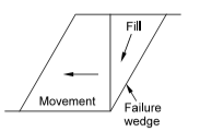
Active earth pressure
Due to excessive pressure of the retained soil, the retaining wall tends to move away from the backfill. Consequently a certain portion of the back fill located immediately behind the retaining wall, gets separated from the rest of the soil mass and hence the earth pressure on the retaining wall decreases. The wedged shaped portion of the back fill tending to move with the wall, is called a failure wedge. The retaining wall is kept in equilibrium by the resisting force developed due to shear strength of the soil along the plane of the failure wedge in a direction away from the retaining wall. There is a limit with which the retaining wall may move away from the back fill, thereby limiting the pressure. The minimum pressure exerted by the soil on the retaining wall, is called active earth pressure.
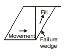
Passive earth pressure
Whenever the retaining wall moves towards the backfill due to any natural cause, the earth pressure increases because the retaining soil gets compressed and the resulting shearing strength develops along the plane of the failure wedge in the direction towards retaining wall. The pressure reaches a maximum limit when the shearing resistance of the soil has been fully mobilised. The maximum earth pressure due to maximum shear stress on the retaining wall, is called passive earth pressure.
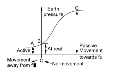
Earth pressure at rest
As active earth pressure is accompanied by the movement of the retaining wall away from the back fill and passive earth pressure is accompanied by the movement of the retaining wall towards the back fill, thus, there occurs an intermediate situation when the retaining wall does not move due to earth pressure but remains perfectly stationary. The pressure which develops due to back fill at zero movement, is called earth pressure at rest. Its value is higher than limiting active pressure but less than the passive pressure. Example of earth pressure at rest: Abutments of a bridge are required to keep its position in tact to support bridge. So abutments are designed for ‘Earth pressure at rest’.
STABILITY OF SLOPES
A slope is an inclined boundary surface between air and the body of an earthwork e.g. high ways cut or fill, railway cut or fill, earth dams, levees and river training works.
Classification of factors leading to instability
(1) Factors causing increased stress
- Increased unit weight of soil by wetting
- Added external load (moving loads, building etc.)
- Steep end slopes either by excavation or by erosion
- Shock loads
(2) Factors causing reduction in strength
Loss of strength may occur due to
- vibrations and earthquakes
- increase in moisture content
- increase in pore pressure
- loss of cementing materials
Stability of Slope of Earth
Dam Earth dams must be safe against slope and foundation failure for all operating conditions. There are three generally recognized critical stages based on pore pressure condition for which the stability of the embankment should be ascertained. These three situations are
- end of construction
- steady state seepage
- rapid drawdown
Usually construction pore pressure reach their maximum values when the embankment reaches maximum height. After the reservoir has been filled for a long time, pore pressures are determined by steady-stage seepage conditions and may be estimated by the construction of flow net. Rapid lowering of the reservoir produces the third critical situations, particularly for low permeable soils. The upstream slope stability may be critical for the construction or rapid drawdown condition. The downstream slope should be checked for the construction and steady-seepage condition.
SOIL MECHANICS IES MASTER GATE STUDY MATERIAL PDF: DOWNLOAD LINK
GEOTECHNICAL ENGINEERING ACE ACADEMY GATE STUDY MATERIALS PDF: DOWNLOAD LINK
SOIL MECHANICS GATE 2020 CIVILENGGFORALL STUDY MATERIAL PDF: DOWNLOAD LINK
FOUNDATIONS
The lower part of a structure that transmits the load, of the superstructure and also its own weight to the soil or rock, is called foundation.
Types of Foundations
(1) Footings – The direct load bearing structure which is constructed as a spread under the base of a wall is called footing.
(2) Combined footings – The combination of two or more footings joined together to form a small mat, is called combined footing.
(3) Strip foundations – The foundation whose length is considerably greater than its width is called strip or continuous foundation.
(4) Raft or Mat foundations – The foundation which supports a large number of footing of loads of a single unit and covers the whole loaded area is called raft foundation. Raft footing is a combined footing that covers the entire area beneath a structure and supports all the walls and columns. I f allowable soil pressure is low, or building loads are heavy, then use of spread footings would cover more than one-half of the area and it may prove more economical to use raft foundation.
Usually, rafts are designed as reinforced concrete flat slabs. If centre of gravity of loads coincide with the centroid of the raft, then upward load regarded as a uniform pressure is equal to downward load divided by the area of the raft. The raft is subdivided into a series of continuous beams (strips) centred on the appropriate column rows. The raft may also be designed as inverted slab, using heavy beams from column to column.
Design of Raft footings (As per I S: 2950 1965)
The maximum differential settlement in foundation on clayey soils and sands should not exceed 40 mm and 25 mm respectively. Maximum settlement should generally be limited to the following values. Raft foundation on clay: 65 to 100 mm Raft foundation on sand: 40 to 65 mm Methods for design of raft foundations (i) Conventional method (ii) Soil line method
(5) Pile foundation – The foundation which is provided in soils incapable to transmit the structural load to suitable stratum by inserting relatively slender structural elements called piles, is called pile foundation.
Classification of pile foundations
- End bearing piles: The piles which act as column and transmit the load through weak soil to a firm stratum at a greater depth, are called end bearing piles.
- Friction piles: The piles which carry the structural load by the friction between the surfaces of the piles and the surrounding soil, are called friction piles.
- Compaction piles: The friction piles which are driven into cohesionless soil for increasing the shear strength of the soils by compaction, are called compaction piles.
Three Principal Modes of Shear Failure Under Footing
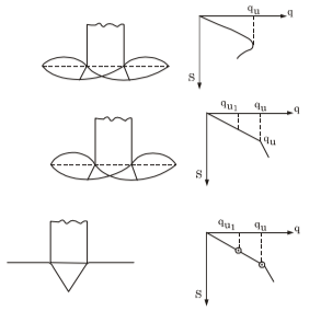
- General shear failure – It is a characteristic of narrow footing of shallow depths resting on strong dense soil that are relatively incompressible.
- Local shear failure – For weaker, more compressible soil and wider or deeper footings, the failure may be taken as local shear failure or punching shear failure. Local shear failure is characterized by well defined slip lines below the footing but extending only a short distance into the soil mass.
- Punching shear failure – In highly compressible soils the punching shear mode of failure results. This is characterized by lack of a well defined slip line below the footing. Vertical movement of footing is primarily due to the compression of soil below the footing with the soil on the side not being involved.
FOUNDATION ENGINEERING CIVIL ENGINEERING GATE 2020 STUDY MATERIAL FREE DOWNLOAD PDF
DOWNLOAD LINK : CLICK HERE
PASSWORD : CivilEnggForAll
NOTE: This book includes the MCQ and previous years GATE questions along with solutions of Soil Mechanics GATE 2020 also.
OTHER USEFUL BOOKS
- CIVIL ENGINEERING TEXTBOOKS WITH DOWNLOAD LINKS
- IES MASTER CIVIL ENGINEERING GATE STUDY MATERIALS PDF
- ACE ACADEMY CIVIL ENGINEERING GATE STUDY MATERIALS PDF
- RAJASTHAN STAFF SELECTION BOARD (RSSB) JUNIOR ENGINEER DIPLOMA CIVIL ENGINEERING EXAM 2022 – HINDI & ENGLISH MEDIUM SOLVED PAPER – FREE DOWNLOAD PDF (CivilEnggForAll.com)
- ISRO TECHNICAL ASSISTANT EXAM 2022 – CIVIL ENGINEERING – HINDI & ENGLISH MEDIUM – SOLVED PAPER – FREE DOWNLOAD PDF (CivilEnggForAll.com)
- MADHYA PRADESH PUBLIC SERVICE (MPPSC) COMMISSION – ASSISTANT ENGINEER EXAM – MPPSC AE 2021 CIVIL ENGINEERING – SOLVED PAPER WITH EXPLANATIONS – PDF FREE DOWNLOAD
- BIHAR PUBLIC SERVICE COMMISSION (BPSC) ASSISTANT ENGINEER EXAM – 2022 – CIVIL ENGINEERING – SOLVED PAPER – FREE DOWNLOAD PDF (CivilEnggForAll.com)
- ODISHA PUBLIC SERVICE COMMISSION – OPSC AEE PANCHAYATI RAJ EXAM 2021 – SOLVED PAPER WITH EXPLANATION – FREE DOWNLOAD PDF