
CONTENTS
- DESIGN OF TENSION MEMBERS
- FACTOR OF SAFETY
- LOAD FACTOR
- TYPES OF TENSION MEMBERS
- DESIGN OF COMPRESSION MEMBERS
- ANGLE STRUTS
- LACINGS
- WELDED CONNECTIONS
- DESIGN OF BEAM AND BEAM MEMBERS
- DESIGN OF CONNECTIONS – COLUMN SLABS AND GUSSETED BASES
- DESIGN OF BEAMS
- DESIGN OF SEMI RIGID AND RIGID CONNECTIONS
- WELDING
- DESIGN OF PLATE GIRDERS
- DESIGN OF ROOF TRUSSES
- BUILT-UP GIRDERS
DESIGN OF TENSION MEMBERS
Design consists of
- choice of materials,
- determination of loads,
- analysis of the structure under the most unfavourable loading combination, and
- design of elements, joints, etc., of the structure
Methods of design
All parts of the steel framework of a structure should be capable of sustaining the most adverse combination of the dead loads, superimposed roof and floor loads, wind loads, seismic forces where applicable and any other forces or loads to which the building may be reasonably subjected without exceeding the permissible stresses.
Steel structures may be proportioned based on simple design, semi-rigid design, full-rigid design and plastic design (or) plastic theory.
DESIGN OF STEEL STRUCTURES IES MASTER GATE STUDY MATERIAL PDF: CLICK HERE
Simple Design
This method applies to structures in which the end connections between members are such that the structure will not develop restraint moments adversely affecting the members and the structure as a whole, and in consequence the structure may, for the purpose of design, be assumed to be pin jointed.
Assumptions:
- The beams are simply supported,
- All connections of beams, girders or trusses are virtually flexible and are proportioned for the reaction shears applied with the appropriate eccentricity,
- The members in compression are subjected to forces applied with appropriate eccentricities combined with appropriate effective lengths,
- The members in tension are subjected to longitudinal forces applied over the net area of the section, and
- The plane sections normal to the axis remain plane after bending.
Semi -Rigid Design
This method permits a reduction in the maximum bending moment in beams suitably connected to their supports, so as to provide a degree of direction fixity, in the case of triangulated frames, it permits account being taken of the rigidity of the connections and the moment of intersection of members.
Fully Rigid Design
This method as compared to the methods of simple and semi-rigid designs gives the greatest rigidity and economy in the weight of steel used when applied in appropriate cases. The end connections of members of the frame should have sufficient rigidity to hold the original angles between such members and the members they connect virtually unchanged. The design is generally based on theoretical methods of elastic analysis and the calculated stress should conform to the provisions of the relevant code.
DESIGN OF STEEL STRUCTURES ACE GATE STUDY MATERIAL PDF: CLICK HERE
Design based on Plastic Theory
Assumptions:
- the plastic range is entered on reaching the yield point,
- strain hardening can be ignored,
- stress-strain relation for tension is the same as that for compression, and
- plane sections remain plane.
Safety Concept
There will be a gap between the internal load and the internal resistance. The gap is covered in either of the two ways:
- In elastic design the allowable stresses are taken less than the strength of the material by an appropriate factor called ‘Factor of Safety’,
- In ultimate strength design, the internal load is increased by a factor called the ‘Load Factor’, whereas the ultimate strength is computed on the basis of yield or buckling strength.
Factor of Safety
In the elastic design of steel structures, the factor of safety is applied on the yield stress of the material to obtain the working stress or permissible stress in the material. The value of factor of safety is decided considering the followings:
- The average strength of materials is determined after making tests on number of specimens. The strengths of different specimens of given structural material are not identical.
- The values of design loads remain uncertain, but values of dead loads can be determined correctly. But live load, impact load, wind load, snow load, etc., cannot be determined with certainty since these depend upon statistics available. The probable values of these loads are only determined.
- The values of internal forces in many structures depend upon the methods of analysis. The degree of precision of different methods varies. The methods involving detailed analysis are more precise. In case, analysis of the structure is done precisely, a small value of factor of safety may be adopted.
- During fabrication, structural steel is subjected to different operations. The punching of a hole in a structural element distorts the surrounding material and causes high residual stresses. The warping and buckling of elements may take place during welding. The welding leaves high residual stresses. Structural elements are subjected to uncertain erection stress.
- The variations in temperatures and settlement of supports are uncertain. Many times, a well designed structure is damaged because of these effects. The strength of materials decreases because of corrosion. The extent of corrosion is more, when a structure is located in industrial areas and exposed to chemical wastes.
- The failure of some structures or some elements of a structure is less serious and less disastrous than the failure of large structures or a main element of a structure.
DESIGN OF STEEL STRUCTURES MADE EASY GATE NOTES PDF: CLICK HERE
Tension Members
A tension member is defined as a structural member subjected to tensile force in a direction parallel to its longitudinal axis. A tension member is also called a tie member or simply a tie.
Types of Tension Members
The types of structure and method of end connections determine the type of a tension member. Tension members used may be broadly grouped into four groups:
- wires and cables,
- rods and bars,
- single-structural shapes and plates,
- built-up members.
Wires and cables
The wire types are used for hoists, derricks, rigging slings, guy wires and hangers for suspension bridges.

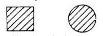
Rods and bars
The square and round bars as shown in Figures are quite often used for small tension members. The round bars with threaded ends are used with pin-connections at the ends instead of threads. The ends of rectangular bars or plates are enlarged by forging and bored to form eye bars. The eye bars are used with pin connections. The rods and bars have the disadvantage of inadequate stiffness resulting in noticeable sag under the self-weight.
Single-structural shapes and plates
The single structural shapes viz., angles sections and tee-sections as shown in figures are used as tension members. The angle sections are considerably more rigid than the wire ropes, rods and bars. When the length of tension member is too long, then, the single angle section also becomes flexible. The single angle sections have the disadvantage of eccentricity in both planes in a riveted connection. The channel section has eccentricity in one axis only. Single channel sections have high rigidity in the direction of web and low rigidity in the direction of flange. Occasionally, I-sections are also used as tension members. The I-sections have more rigidity, and single I-sections are more economical than built-up sections.

Built-up Members
Two or more than two members are used to form built-up members. When the single rolled steel sections cannot furnish the required area, then built-up sections are used. The double angle sections of unequal legs shown in the figure are extensively used as tension members in the roof trusses. The angle sections are placed back-to-back on two sides of a gusset plate. When both the angle sections are attached on the same sides of the gusset, then, built-up section has eccentricity in one plane and is subjected to tension and bending simultaneously.
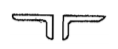
The two angle sections may be arranged in the star shape (i.e., the angles are placed diagonally opposite to each-other with leg on outer sides). The star shape angle sections may be connected by batten plates. The batten plates are alternately placed in two perpendicular directions. The star arrangement provides a symmetrical and concentric connection.
DESIGN OF STEEL STRUCTURES STUDY MATERIAL FOR SSC JE PDF CIVILENGGFORALL
DOWNLOAD LINK : CLICK HERE
PASSWORD : CivilEnggForAll
OTHER USEFUL BOOKS
- RAJASTHAN STAFF SELECTION BOARD (RSSB) JUNIOR ENGINEER DIPLOMA CIVIL ENGINEERING EXAM 2022 – HINDI & ENGLISH MEDIUM SOLVED PAPER – FREE DOWNLOAD PDF (CivilEnggForAll.com)
- ISRO TECHNICAL ASSISTANT EXAM 2022 – CIVIL ENGINEERING – HINDI & ENGLISH MEDIUM – SOLVED PAPER – FREE DOWNLOAD PDF (CivilEnggForAll.com)
- MADHYA PRADESH PUBLIC SERVICE (MPPSC) COMMISSION – ASSISTANT ENGINEER EXAM – MPPSC AE 2021 CIVIL ENGINEERING – SOLVED PAPER WITH EXPLANATIONS – PDF FREE DOWNLOAD
- BIHAR PUBLIC SERVICE COMMISSION (BPSC) ASSISTANT ENGINEER EXAM – 2022 – CIVIL ENGINEERING – SOLVED PAPER – FREE DOWNLOAD PDF (CivilEnggForAll.com)
- ODISHA PUBLIC SERVICE COMMISSION – OPSC AEE PANCHAYATI RAJ EXAM 2021 – SOLVED PAPER WITH EXPLANATION – FREE DOWNLOAD PDF