
CONTENTS
- Bending Moment and Shear Force
- Simple Stress
- Shearing Stress or Tangential Stress
- Stress and Strain in Two Dimensions
- Transformation of Strain Components
- Elastic Constants
- Theories of Failure
- Simple Bending Theory
- Bending Stress
- Flexural and Shear Stresses
- Shear Centre
- Uniform Torsion
- Compound Shafts
- Columns
- Analysis of Long Columns by Euler’s Formula
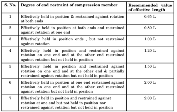
- Effective Length of Compression Members
- Long Column Under Eccentric Loading
- Combined Direct and Bending Stresses
- Load Acting Eccentrically to One Axis
- Load Acting Eccentrically to Both Axes
- Condition for No Tension in the Section

Stress at a point
- Average stress over an area is obtained by dividing the force by the area over which it acts.
- If the average stress is constant over the area, the stress is said to be uniform.
- If the stress is not uniform, then stress at a point is determined. So, stress at a point defines the uniform stress distributed over a differential area (or permitting the area enclosing the point to approach zero as a limit).
IES MASTER CIVIL ENGINEERING GATE STUDY MATERIALS PDF: CLICK HERE
Variation of stress with inclination of element
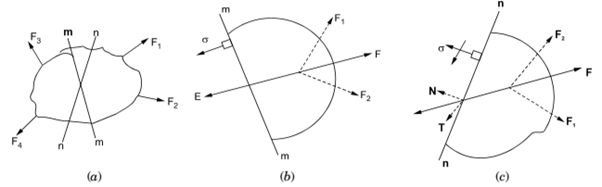
There are two sections m-m and n-n passing through the body on which several forces acts. Section m-m is perpendicular to the resultant F of F1 and F2 and section n-n is inclinded to F. Thus, element in Fig. (b) is subjected only to a normal stress while element in Fig. (c) is subjected to both normal and shearing stresses.
Note: Thus, at same position in a stressed body, the stresses on an element vary with the orientation of the element.
Rules for drawing Mohr’s circle
- On rectangular α – τ axis, plot the points having co-ordinates A (αx, τxy) and B (αy, τyx). Assume tension as plus, compression as minus, and shearing stress as plus when its moment about centre is clockwise.
- Draw a straight line joining these points which gives the diameter of a circle whose centre is an σ-axis.
- The radius of the circle to any point on its circumference represents the axis directed normal to the plane whose stress components are given by the co-ordinates of that point.
- The angle between the radii to selected points on Mohr’s circle is twice the angle between the normals to the actual planes represented by these points.
SIMPLE BENDING THEORY
Assumptions
- Plane sections of the beam remain plane.
- Material of the beam is homogenous and obeys Hooke’s law
- Modulii of elasticity for tension and compression are equal.
- Beam is straight and of constant cross-section.
- Plane of loading must contain a principal axis of the beam cross-section and the load must be perpendicular to the longitudinal axis of the beam.
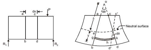
The stress caused by the bending moment are called bending or flexure stresses and relation between these stresses and the bending moment is expressed by the flexure formula. Two sections ab and cd and their exaggerated form are shown. The plane containing fibres like ef is called neutral surface because such fibres remain unchanged in length.
SHEAR CENTRE
The shear centre is a point of intersection of the bending axis and the plane of transverse section. Shear centre of a section can be defined as a pint about which the applied force is balanced by the set of shear forces obtained by summing the shear stresses over the section (for unsymmetrical section such as angle section and channel section, summation of shear stresses in each leg gives a set of forces which should be in equilibrium with the shear force). It is also known as “centre of twist”.
In case of beam having two axes of symmetry, the shear centre coincides with the centroid. In case of sections having one axis of symmetry, the shear centre does not coincide with the centroid but lies on the axis of symmetry. When the load passes through the shear centre then there will be only bending in the cross-section and no twisting.
ACE ACADEMY CIVIL ENGINEERING GATE STUDY MATERIALS: CLICK HERE
COLUMNS
A column is a compression member that under gradually increasing loads it fails by buckling at loads considerably less than those required to cause failure by crushing. A compression member is generally considered to be a column when its unsupported length is more than 10 times its lateral dimension.
- Long column fails by buckling.
- Intermediate columns fails by a combination of crushing and buckling.
- Short compression blocks fails by crushing.
Note: An ideal column is homogenous that is initially straight and is subjected to axial compressive loads. However, actual columns have small imperfections of material and fabrication as well as unavoidable accidental eccentricities of load. The initial crookedness of the column, together with the placement of the load, causes an intermediate eccentricity, e with respect to the centroid of a typical section.
STRENGTH OF MATERIALS CIVIL ENGINEERING GATE 2020 STUDY MATERIAL FREE DOWNLOAD PDF
DOWNLOAD LINK : CLICK HERE
PASSWORD : CivilEnggForAll
OTHER USEFUL BOOKS
- CIVIL ENGINEERING TEXTBOOKS WITH DOWNLOAD LINKS
- IES MASTER CIVIL ENGINEERING GATE STUDY MATERIALS PDF
- ACE ACADEMY CIVIL ENGINEERING GATE STUDY MATERIALS PDF
- RAJASTHAN STAFF SELECTION BOARD (RSSB) JUNIOR ENGINEER DIPLOMA CIVIL ENGINEERING EXAM 2022 – HINDI & ENGLISH MEDIUM SOLVED PAPER – FREE DOWNLOAD PDF (CivilEnggForAll.com)
- ISRO TECHNICAL ASSISTANT EXAM 2022 – CIVIL ENGINEERING – HINDI & ENGLISH MEDIUM – SOLVED PAPER – FREE DOWNLOAD PDF (CivilEnggForAll.com)
- MADHYA PRADESH PUBLIC SERVICE (MPPSC) COMMISSION – ASSISTANT ENGINEER EXAM – MPPSC AE 2021 CIVIL ENGINEERING – SOLVED PAPER WITH EXPLANATIONS – PDF FREE DOWNLOAD
- BIHAR PUBLIC SERVICE COMMISSION (BPSC) ASSISTANT ENGINEER EXAM – 2022 – CIVIL ENGINEERING – SOLVED PAPER – FREE DOWNLOAD PDF (CivilEnggForAll.com)
- ODISHA PUBLIC SERVICE COMMISSION – OPSC AEE PANCHAYATI RAJ EXAM 2021 – SOLVED PAPER WITH EXPLANATION – FREE DOWNLOAD PDF