
CONTENTS
- Working Stress And Limit State Method Of Analysis
- Limit State Design
- Design Of Beams
- Design Of Components Of Buildings
- Design Of Compression Member
- Design Of Square Column Footing
- Introduction to IS 456: 2000
- Slender Compression Members
- Design of Singly Reinforced Member
- Design of Doubly Reinforced Members
WORKING STRESS AND LIMIT STATE METHOD OF ANALYSIS
There are three design philosophies relating to reinforced and prestressed concrete:
- Working stress method,
- Ultimate load method, and
- Limit state method.
RCC DESIGN IES MASTER GATE STUDY MATERIAL PDF: CLICK HERE
Working Stress Method
The assumptions made are:
- A section which is plane before bending remains plane after bending,
- Bond between steel and concrete is perfect within the elastic limit of steel,
- Tensile strength of concrete can be ignored,
- Concrete is elastic, i.e. stress in concrete varies linearly from zero at the neutral axis to a maximum at the extreme fibre,
- The modular ratio has the value 280/3σcbc where σcbc is the permissible compressive stress in bending in N/mm2.
According to Indian Standard IS:456, 2000 the permissible compressive stress in bending in concrete is one-third the 28-day cube strength of concrete. The corresponding factor of safety is 1.78 for steel, which is applied on the yield strength of steel in tension.
Drawbacks of the working stress method are:
- Concrete is not elastic, and the stress distribution in the concrete section is not triangular,
- The factor of safety is applied on the stresses, and the different degrees of uncertainties associated with different types of loads is not accounted for, and
- It is difficult to account for shrinkage and creep by calculation of elastic stresses.
Ultimate Load Method
In this method, working loads are increased by suitable factors, known as load factors, to obtain ultimate loads and the structure is designed to resist these loads.
RCC DESIGN ACE ACADEMY GATE STUDY MATERIAL PDF: CLICK HERE
Whitney’s Theory
It is based on the assumption that the ultimate strain in concrete is 0.3 per cent and the compressive stress at the extreme edge corresponds to this strain. Whitney replaced the actual parabolic stress diagram by a rectangular stress diagram such that the centre of gravity of both diagrams lies at the same point and their areas are also equal.
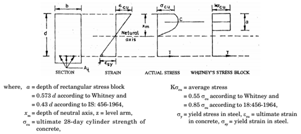
Assumptions
- A section which is plane before bending remains plane after bending.
- At ultimate strength, stresses and strains are not proportional and the distribution of compressive stresses is non-linear in a section subjected to bending. The stress block may be assumed as a rectangle, parabola or any other shape, which gives ultimate strength in reasonable agreement with test results.
- Maximum fibre strength in concrete does not exceed 0.68 σcu As in Whitney’s theory, a rectangular stress block with a = 0.43 d and the average stress = 0.55 σcu can be assumed for analysis.
- Tensile strength of concrete is ignored. Indian Standard, IS:456-2000 stipulated the following conditions for ultimate design load, u:
- for structures in which the effects of wind and earthquake loads can be ignored, u: should be equal to 1.5 D + 2.2, and
- for structures in which earthquake loads should be considered, u should be equal to (1.5 D + 2.2 L + 0.5 W) or (1.5 D + 0.5 L + 2.2 W) whichever gives the critical condition. where, D is dead load, L is live load, and W is wind or earthquake load.
Drawbacks:
- Since the load factor is applied on the working loads, there is no provision to account for the uncertainties associated with variations in material stresses.
- There is no provision in the method for control against excessive deflections.
RCC DESIGN ACE GATE NOTES PDF: CLICK HERE
Limit State Design
The object of limit state design is to achieve an acceptable probability that a structure will not become unserviceable in its lifetime. The condition of a structure when it becomes unserviceable is called a limit state. The most important of these limit states which must be examined in design are:
- Ultimate limit state: Neither the whole structure nor any part of the structure should collapse under foreseeable overload,
- Serviceability limit state of deflection: The deflection of the structure should not adversely affect the appearance of the structure,
- Serviceability limit state of cracking: The cracking of the concrete should not affect the appearance or durability of the concrete,
- Serviceability limit state of vibration: Vibration should not be such as to cause alarm of discomfort to the user.
Therefore, collapse limit state at which the strength must be adequate to carry the loads with due consideration to stability, and serviceability limit state at which the deflection cracking and vibration must not be excessive.
Characteristic Strength
The characteristic strength σk of a material means that value of its strength below which not more than 5% of the test results are expected to fall.
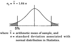
The characteristic strength, σk is usually represented by the 28-day cube strength, σck of concrete, and the yield or 0.2% proof stress, σy, of reinforcement.
RCC DESIGN STUDY MATERIAL FOR SSC JE PDF CIVILENGGFORALL
DOWNLOAD LINK : CLICK HERE
PASSWORD : CivilEnggForAll
OTHER USEFUL BOOKS
- RAJASTHAN STAFF SELECTION BOARD (RSSB) JUNIOR ENGINEER DIPLOMA CIVIL ENGINEERING EXAM 2022 – HINDI & ENGLISH MEDIUM SOLVED PAPER – FREE DOWNLOAD PDF (CivilEnggForAll.com)
- ISRO TECHNICAL ASSISTANT EXAM 2022 – CIVIL ENGINEERING – HINDI & ENGLISH MEDIUM – SOLVED PAPER – FREE DOWNLOAD PDF (CivilEnggForAll.com)
- MADHYA PRADESH PUBLIC SERVICE (MPPSC) COMMISSION – ASSISTANT ENGINEER EXAM – MPPSC AE 2021 CIVIL ENGINEERING – SOLVED PAPER WITH EXPLANATIONS – PDF FREE DOWNLOAD
- BIHAR PUBLIC SERVICE COMMISSION (BPSC) ASSISTANT ENGINEER EXAM – 2022 – CIVIL ENGINEERING – SOLVED PAPER – FREE DOWNLOAD PDF (CivilEnggForAll.com)
- ODISHA PUBLIC SERVICE COMMISSION – OPSC AEE PANCHAYATI RAJ EXAM 2021 – SOLVED PAPER WITH EXPLANATION – FREE DOWNLOAD PDF