
CONTENTS
PROBLEMS, SOLUTIONS, EXAMPLES, EXERCISES, EXERCISE’S HINTS AND EXPLANATIONS OF THE BELOW TOPICS
- Basic Principles
- Maps
- Representative Fraction (R.F.)
- Errors
- Classification of Survey
- Chain Survey
- Compass Survey
- Theodolite Survey
- Tachometric Survey
- Plane Table Survey
- Triangulation Survey
- Photogrammetry

- Local attraction – When a magnetic needle is disturbed from its normal position due to influence of external forces such as electric current or magnetic substances, local attraction is said to have occurred. In such a situation magnetic needle does not point towards North – South.
- Dip – Inclination of the needle with the horizontal is called dip of the needle. The amount of dip is not uniform. It varies in different parts of the earth.
- Magnetic Declination – Horizontal angle between true meridian and magnetic meridian at a place is called magnetic declination. If magnetic meridian is to the right side (eastern side.) of the true meridian, then declination is called positive and if it is to the left side (western side), the declination is called negative.
- Isogonic line – It is an imaginary line drawn through the points of same declination.
- Agonic lines – Lines joining points of zero declination are called agonic lines.
Levelling – It is done to find relative heights and depths of objects on the surface of the earth.
Principle of Levelling – It furnishes a horizontal line of sight and helps in finding vertical distances of the point above or below this line.
Level (Telescope) – It is the instrument used for levelling
Parts of Level: Essentially a level consists of following five parts:
- Telescope to provide a line of sight
- Level tube to make the line of sight horizontal
- Levelling head to bring the bubble in the centre of tube
- Cross bubble tube to provide a horizontal plane
- Tripod to support the instrument.
Types of Levels
Following levels are commonly used:
- Dumpy level
- Wye level
- Cooke’s Reversible level
- Cushing’s level.
- Modern tilting level of Indian Office Pattern.
IES MASTER CIVIL ENGINEERING GATE STUDY MATERIALS PDF: DOWNLOAD LINK
ACE ACADEMY CIVIL ENGINEERING GATE STUDY MATERIALS PDF: DOWNLOAD LINK
Dumpy Level
It is a simple, compact and stable instrument. The telescope is rigidly fixed to its support and it can neither be rotated about its longitudinal axis and nor it can be removed from its support.
Parts of a Dumpy level
- Levelling head
- Telescope
- Eye piece
- Diaphragm screws
- Focussing-screws
- Ray-shade
- Longitudinal/Altitude bubble tube
- Babble tube adjusting screws
- Cross bubble tube
Advantage of Dumpy level
- It is simple in construction with a few movable parts.
- It requires fewer permanent adjustments.
- Adjustment once carried out remains for a longer period.
Levelling Staff
A straight, rectangular wooden rod graduated into meters/feet and further smaller divisions, called levelling staff. Bottom of the levelling staff represents zero-reading. In most common forms, the smallest division is of 5 mm and graduations are in the form of alternate black and white strips. The purpose of a level (instrument) is to establish a horizontal line of sight, and purpose of the levelling staff is to determine the amount by the which station (i.e. foot of the staff) is above or below the line of sight.
Commonly used terms in Surveying
- Level surface: It is a surface parallel to the mean spheroidal surface of the earth. Every point on this surface is equidistant from the centre of the earth. It is normal to the plumbline at all points.
- Level line: It is a line lying in the level surface.
- Horizontal surface: A surface tangential to the level surface at a point is called horizontal surface at that point. It is always perpendicular to the plumbline.
- Horizontal line: Any line lying in the horizontal surface at any point is called horizontal line. It is tangential to the level line.
- Vertical surface: Surface normal to the level surface at any point is called vertical surface.
- Vertical line: Any line in the vertical surface is called a vertical line. It is normal to the level line.
- Datum: It is an imaginary level surface or line from which vertical distances of the points above or below this line are measured. In India, datum surface is taken as mean sea level of Mumbai and is treated as zero. Reduced level of any point is the height of that point above or below any datum. It may be positive or negative depending upon point lying being above or berow the datum.
- Line of collimation: It is an imaginary straight line joining intersection of the cross-hairs at diaphragm to the optical centre of the object – glass and its continuation. It is also called line of sight. It is horizontal when bubble is in the centre.
- Back Sight (B.S.): It is staff reading taken on the point of known R.L. e.g., on a bench mark or on a change point. It is the first staff reading taken after setting and levelling of the instrument.
- Fore Sight (F.S.): It is a staff reading taken on a point whose R.L. is to be determined. It is the last staff reading taken before shifting of the level to another position.
- Intermediate Sight (I .S.): All the readings other than foresight and backsight taken on points of unknown R.L. from the same set – up of the level. In one setting of level, there is only one backsight and one foresight, but there can be any number of intermediate sights.
- Height of Instrument (H .I.): It is R.L. of the line of collimation, when instrument is correctly levelled. It is always with reference to the datum.
- Station: It is the point, where staff is held and reading are taken during process of levelling.
- Change Point (C.P.): It is an intermediate staff station on which two sights F.S. and B.S. are taken and is used for the purpose of changing position of the instrument.
- Bench Mark (B.M): It is a fixed reference point of known elevation. These may be classified as follows: 1. G.T.S. (Great Trigonometrical Survey) bench marks: These are permanently marked. 2. Arbitrary Bench marks 3. Temporary Bench marks.
- Parallax: It is the relative motion of the image with respect to the cross-hairs. When image formed by the object glass does not fall in the plane of the diaphragm there is said to be parallax. It is due to faulty focussing of the object glass.
Reduced Levels
Following two methods are used
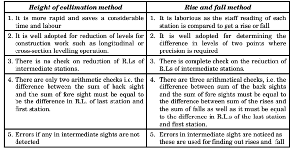
- Rise and Fall Method: In this method, difference of level between two consecutive points for each setting of the instrument, is obtained by comparing their staff readings. Difference between their staff readings indicates a rise if back staff reading is more than the fore sight and a fall if it is less than the fore sight. Algebraic sum of rises and falls, gives difference in levels between starting and closing points.
- Height of Collimation Method: In this method, height of the instrument is calculated for first setting of instrument by adding back sight to the reduced level of the given Bench Mark. Reduced level of the first station is obtained by subtracting its fore sight from the instrument height (H.I.)
Comparison between Height of Collimation Method and Rise & Fall Method
ACE ACADEMY CIVIL ENGINEERING GATE HANDWRITTEN CLASSROOM NOTES PDF: DOWNLOAD LINK
MADE EASY CIVIL ENGINEERING GATE HANDWRITTEN CLASSROOM NOTES PDF: DOWNLOAD LINK
Classification of Spirit Levelling
- Differential Levelling – The operation of levelling to determine elevation. reduced – level of points at some distance apart to establish Bench Marks in the area, is called differential levelling or fly levelling or simple fly levelling.
- Profile Levelling – The operation of levelling carried out to determine the elevations of the points at known distances apart, and also other salient features, along a given straight line is called profile levelling or longitude levelling.
- Reciprocal Levelling – The operation of levelling in which difference in elevations between the points is according determined by two sets of reciprocal observations, is called reciprocal levelling. It is employed when it is not possible to set up the level between two points due to an intervening obstruction such as large water bodies. It is used to obtain accuracy and a eliminate the following
- Error in instrument adjustment
- Combined effect of earth’s curvature and the refraction the atmosphere
- Variations in the average rejection.
Contour – It is an imaginary line on the ground joining points of equal elevations. Maps representing horizontal as well as vertical relative positions of points are called topographic maps.
Contour interval – Vertical distance between any two consecutive contours is called contour interval. It depends upon following:
- Scale and purpose of the map
- Nature of ground
- Availability of fund and time.
Horizontal Equivalent – It is the shortest horizontal distance between two consecutive contours.
Contour gradient – It is an imaginary line lying on the surface of the earth and maintaining a constant inclination to the horizontal.
Characteristics of Contours
- Two contours of different elevations do not cross each other except in the case of an overhanging cliff.
- Contours of different elevations, do not combine to from one contour except in the case of a vertical cliff.
- Contours drawn closer depict a steep slope and if drawn far apart, it represent a gentle slope.
- Contours equally spaced depict a uniform slope. When contours are parallel, equidistant and straight, they represent an inclined plane surface.
- A contour at any point is perpendicular to the line of the steepest slope at the point.
- A contour must close itself or go out of the limit of the map.
- A set of ring contours with higher values inside, depict hill whereas a set of ring contours with lower values inside, depict pond or depression.
- When contours cross a ridge or V – Shaped valley, these form sharp V – shaped across them. Contours represent a ridge line, if concavity of higher value contour lies towards next lower value contour and on the other hand these represent a valley if concavity of the lower value contour, lies towards higher value contour.
- The same contour must appear on both the sides of a ridge or a valley.
Uses of Contour Maps
- With the knowledge of characteristics of contours, it is easy to visualise whether contrary is flat, undulating or mountainous.
- To decide most economical and suitable sites for engineering works such as canal, sewer reservoir, road, railway, etc.
- To determine catchment area of the drainage basin and hence capacity of the proposed reservoir.
- To compute earth work required for filling or cutting along the linear alignment of projects such as canals, roads, etc.
- To ascertain inter-visibility of the points.
- To trace a contour gradient for road alignments.
- To draw longitudinal sections and cross – sections to ascertain nature of the ground.
- To calculate water capacities of reservoirs.
SURVEYING TEXTBOOKS PDF: CLICK HERE
SURVEYING MADE EASY GATE NOTES PDF: CLICK HERE
SURVEYING ACE ACADEMY GATE NOTES PDF: CLICK HERE
THEODOLITE SURVEY
Theodolite is the most precise instrument designed for measurement of horizontal and vertical angles.
Commonly Used Terms in Theodolite
- Centring: It means setting the theodolite exactly over an instrument-station so that its vertical axis lies immediately above the station mark. It can be done by means of plumb-bob suspended from the vertical axis of the theodolite.
- Transiting: It is also called reversing. It is the process of turning the telescope about its horizontal axis through 180 degrees in the vertical plane.
- Swinging the Telescope: It means turning the telescope about its vertical axis in the horizontal plane.
- Face Left and Face Right: If vertical circle of the instrument is on the left of the observer while taking a reading, the position is called face left and the observation taken on the horizontal or the vertical circle in this position, is called face left observation. Similarly if vertical circle of the instrument is on the right of the observer while taking a reading, the position is called face right.
- Changing Face: It is the operation of bringing the vertical circle to the right of the observer, if originally it is to the left, and vice-versa.
- Line of Collimation: It is the imaginary line joining the intersection of the cross-hairs of the diaphragm to the optical centre of the object-glass and in its continuation. It is also called line of sight.
- Axis of the Telescope: It is also an imaginary line joining the optical centre of object-glass to the centre of eye-piece.
- Axis of the Ievel tube: It is also called bubble line. It is a straight line tangential to the longitudinal curve of the level lube at the centre of the tube. It is horizontal when the bubble is central.
- Vertical Axis: It is the axis about which the telescope can be rotated in the horizontal plane.
- Horizontal Axis: It is also called trunion axis or transverse axis. It is the axis about which the telescope can be revolved in the vertical plane.
SURVEYING PART-2 CIVIL ENGINEERING GATE 2020 STUDY MATERIAL FREE DOWNLOAD PDF
DOWNLOAD LINK : CLICK HERE
PASSWORD : CivilEnggForAll
DOWNLOAD SURVEYING PART-1 – CLICK HERE
OTHER USEFUL BOOKS
- CIVIL ENGINEERING TEXTBOOKS WITH DOWNLOAD LINKS
- IES MASTER CIVIL ENGINEERING GATE STUDY MATERIALS PDF
- ACE ACADEMY CIVIL ENGINEERING GATE STUDY MATERIALS PDF
- RAJASTHAN STAFF SELECTION BOARD (RSSB) JUNIOR ENGINEER DIPLOMA CIVIL ENGINEERING EXAM 2022 – HINDI & ENGLISH MEDIUM SOLVED PAPER – FREE DOWNLOAD PDF (CivilEnggForAll.com)
- ISRO TECHNICAL ASSISTANT EXAM 2022 – CIVIL ENGINEERING – HINDI & ENGLISH MEDIUM – SOLVED PAPER – FREE DOWNLOAD PDF (CivilEnggForAll.com)
- MADHYA PRADESH PUBLIC SERVICE (MPPSC) COMMISSION – ASSISTANT ENGINEER EXAM – MPPSC AE 2021 CIVIL ENGINEERING – SOLVED PAPER WITH EXPLANATIONS – PDF FREE DOWNLOAD
- BIHAR PUBLIC SERVICE COMMISSION (BPSC) ASSISTANT ENGINEER EXAM – 2022 – CIVIL ENGINEERING – SOLVED PAPER – FREE DOWNLOAD PDF (CivilEnggForAll.com)
- ODISHA PUBLIC SERVICE COMMISSION – OPSC AEE PANCHAYATI RAJ EXAM 2021 – SOLVED PAPER WITH EXPLANATION – FREE DOWNLOAD PDF