
CONTENTS
- Tension Member
- Net Sectional Area
- Combined Axial And Bending Tensile Stresses
- Slenderness Ratio (l)
- Design of Axially Loaded Tension Member
- Compression Members
- Lacings and Battens for Built-up
- Compression Members
- Design of Beams and Beam Columns
- Design of Connections: Column Slabs and Gusseted Bases
- Design of Semi-rigid and Rigid Connections
- Riveting and Bolting
- Welding
- Plate Girders
- Roof Trusses
- Plastic Analysis of Beams and Portals
- Plastic Hinge and Mechanism

TENSION MEMBER
It is defined as a structural member subjected to tensile force in a direction parallel to its longitudinal axis. A tension member is also called tie member or simply a tie.
Types of Tension Members The types of structure and method of end connections determine type of a tension member. Tension members used may be broadly grouped into following four groups:
Wires and Cables
These are used for hoists, derricks, rigging slings, guy wires and hangers for suspension bridges.
Rods and Bars
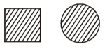
Square and round bars as shown in figures are quite often used for small tension members. Round bars with threaded ends are used with pin-connections at the ends instead of threads. Ends of rectangular bars or plates are enlarged by forging and bored to form eye bars. Eye bars are used with pin connections. Rods and bars have the disadvantage of inadequate stiffiness resulting in noticeable sag under the self-weight.
Single-structural shapes and Plates
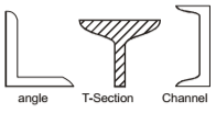
Single structural shapes viz., angles sections and tee-sections as shown in figures are used as tension members. Angle sections are considerably more rigid than the wire ropes, rods and bars. When length of tension member is too long, then single angle section also becomes flexible. Single angle sections have disadvantage of eccentricity in both planes in a riveted connection. Channel section has eccentricity in one axis only. Single channel sections have high rigidity in the direction of web and low rigidity in the direction of flange. Occasionally, I -sections are also used as tension members. I -sections have more rigidity, and single I-sections are more economical than built-up sections.
Built-up Members
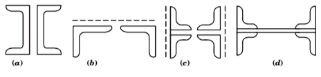
Two or more than two members are used to form built-up members. When single rolled steel sections cannot furnish the required area, then built-up sections are used. Double angle sections of unequal legs shown in the figure are extensively used as tension members in the roof trusses. The angle sections are placed back-to-back on two sides of a gusset plate. When both the angle sections are attached on the same sides of the gusset, then built-up section has eccentricity in one plane and is subjected to tension and bending simultaneously. The two angle sections may be arranged in the star shape (i.e., angles are placed diagonally opposite to each-other with leg on outer sides). The star shape angle sections may be connected by batten plates. The batten plates are alternately placed in two perpendicular directions. The star arrangement provides a symmetrical and concentric connection. Two channel sections as shown in the Fig. (a) are used in the two-plane trusses, where two parallel gussets are used at each connection. Two-angle sections as shown in Fig. (b) have the advantage that distance between them could be adjusted to suit connecting members at their ends. Four-angle sections as shown in Fig. (c) are also used in the two-plane trusses. The angles are connected to two parallel gusset. For angle sections connected by plates as shown in Fig. (d) are used as tension members in bridge girders.
A built-up section may be made of two channels placed back-to-back with a gusset in between them. Such sections are used for medium loads in a single-plane truss. In two-plane trusses, two channels are arranged at a distance with their flange turned inward. It simplifies the transverse connections, and also minimizes lacing. Flanges of two channels are kept outwards, as in the case of chord members of long-span girders, in order to have greater lateral rigidity.
Heavy built-up tension members in the bridge girder trusses are made of angles and plates. Such members can resist compression if reversal of stress takes place.
– IES MASTER CIVIL ENGINEERING GATE STUDY MATERIALS PDF: CLICK HERE
– ACE ACADEMY CIVIL ENGINEERING GATE STUDY MATERIALS PDF: CLICK HERE
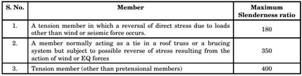
SLENDERNESS RATIO (L)
The slenderness ratio of a tension member is the ratio of its unsupported length (l) to its least radius of gyration (r)
Maximum Slenderness Ratio
DESIGN OF AXIALLY LOADED TENSION MEMBER
The following steps are followed while designing can axially loaded tension member.
- Calculate the net sectional area required as, Anet required = axial force/Permissible tensile stress
- Try a suitable section having sectional area 25% to 40% larger than the Anet required.
- Calculate the Anet available in the trial section.
- The trial section will be suitable if Anet available ≥ Anet required
- Check the slenderness ratio when the reversal of load may occur as per the table given above.
- Design end connection.
Lug Angle
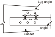
The Lug Angle is a short length of an angle section used at a joint to connect the outstanding leg of a member, thereby reducing the length of joint. Lug Angles are also not very efficient in transmitting loads and a certain eccentricity is caused between b/w the load and C.G. of the rivet group. The use of lug angles is therefore avoided in general. A Lug Angle is provided at the beginning of a joint so that it can be effective in sharing bad.
Design of lug angles Indian Standard IS:800 specifies followings
- Lug angles connecting a channel-shaped member should, as far as possible, be disposed symmetrically with respect to the section of the member.
- In the case of angle members, lug angles and their connections to the gusset or any other supporting member should be capable of developing a strength not less than 20% in excess of the force in the outstanding leg of the angle and attachment of the lug angle to the angle member should be capable of developing a strength 40% in excess of that force.
- In the case of channel sections, lug angles and their connections to the gusset or any other supporting member should be capable of developing a strength of not less than 10% in excess of the force not accounted for by the direct connection of the member, and the attachment of the lug angles to the member should be capable of developing a strength 20% in excess of that force.
- In no case should fewer than two bolts or rivets be used for attaching the lug angle, to the gusset or another supporting member.
- Effective connection of the lug angle should, as far as possible, terminate at the end of the member connected and the fastening of the lug angle to the member should preferably start in advance of the direct connection of the member to the gusset or other supporting member.
- Where lug angles are used to connect an angle member, whole area of the member should be taken as effective, i.e. Anet = gross area – deduction for holes.
STEEL STRUCTURES ACE ACADEMY GATE NOTES PDF: CLICK HERE
STEEL STRUCTURES MADE EASY GATE NOTES PDF: CLICK HERE
Tension Splice
Strength of the splice plates and the rivets connecting them with the member should atleast be equal to the design load of the tension member. When tension members of different sizes have to be connected, filler plates may be used to bring the member in level. Rivets or bolts carrying a calculated shear stress through a packing more than 6 mm thick should be increased above the number required by normal calculations by 2.5% for each 2 mm thickness of packing. For double shear connections packed on both sides, the number of additional rivets or bolts required is determined from the thickness of the thicker packing. Additional rivets or bolts should preferably be placed in an extension of the packing.
Riveted and Welded Connections
In a riveted connection, rivets are placed on the gauge lines of the angles and this results in small eccentricity of load on the joint as well as the member. In the welded connection, lengths of the welds can be adjusted so that centre of gravity of the joint lies on the line passing through centre of gravity line of the member.
COMPRESSION MEMBERS
A structural member loaded axially in compression is generally called compression member. The structural members carrying compressive load in truss is called STRUTS. Vertical compression members in buildings are called columns, posts or stanchions. The main Compression members in roof trusses are called Raftor and in a crane is called a boom.
COLUMN
Short columns are subject to crushing and behave like members under pure compression. Long columns tend to buckle out of the plane of the load axis.
STEEL STRUCTURES CIVIL ENGINEERING GATE 2020 STUDY MATERIAL FREE DOWNLOAD PDF
DOWNLOAD LINK : CLICK HERE
PASSWORD : CivilEnggForAll
OTHER USEFUL BOOKS
- CIVIL ENGINEERING TEXTBOOKS WITH DOWNLOAD LINKS
- IES MASTER CIVIL ENGINEERING GATE STUDY MATERIALS PDF
- ACE ACADEMY CIVIL ENGINEERING GATE STUDY MATERIALS PDF
- RAJASTHAN STAFF SELECTION BOARD (RSSB) JUNIOR ENGINEER DIPLOMA CIVIL ENGINEERING EXAM 2022 – HINDI & ENGLISH MEDIUM SOLVED PAPER – FREE DOWNLOAD PDF (CivilEnggForAll.com)
- ISRO TECHNICAL ASSISTANT EXAM 2022 – CIVIL ENGINEERING – HINDI & ENGLISH MEDIUM – SOLVED PAPER – FREE DOWNLOAD PDF (CivilEnggForAll.com)
- MADHYA PRADESH PUBLIC SERVICE (MPPSC) COMMISSION – ASSISTANT ENGINEER EXAM – MPPSC AE 2021 CIVIL ENGINEERING – SOLVED PAPER WITH EXPLANATIONS – PDF FREE DOWNLOAD
- BIHAR PUBLIC SERVICE COMMISSION (BPSC) ASSISTANT ENGINEER EXAM – 2022 – CIVIL ENGINEERING – SOLVED PAPER – FREE DOWNLOAD PDF (CivilEnggForAll.com)
- ODISHA PUBLIC SERVICE COMMISSION – OPSC AEE PANCHAYATI RAJ EXAM 2021 – SOLVED PAPER WITH EXPLANATION – FREE DOWNLOAD PDF