
CONTENTS
Basic concepts of surveying
Definition – Basic measurements – Control networks – Locating position – Locating topographic detail – Computer systems – DGM – CAD – GIS – Vector/raster – Topology – Laser scanner – Summary – Units of measurement – Significant figures – Rounding off numbers – Errors in measurement – Indices of precision – Weight – Rejection of outliers – Combination of errors
Vertical control
Introduction – Levelling – Definitions – Curvature and refraction – Equipment – Instrument adjustment – Principle of levelling – Sources of error – Closure tolerances – Error distribution – Levelling applications – Reciprocal levelling – Precise levelling – Digital levelling – Trigonometrical levelling – Stadia tacheometry
Distance
Tapes – Field work – Distance adjustment – Errors in taping – Accuracies – Electromagnetic distance measurement (EDM) – Measuring principles – Meteorological corrections – Geometrical reductions – Errors and calibration – Other error sources – Instrument specifications – Developments in EDM – Optical distance measurement (ODM)
Angles
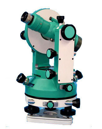
The theodolite – Instrumental errors – Instrument adjustment – Field procedure – Measuring angles – Sources of error
Position
Introduction – Reference ellipsoid – Coordinate systems – Local systems – Computation on the ellipsoid – Datum transformations – Orthomorphic projection – Ordnance Survey National Grid – Practical applications – The Universal Transverse Mercator Projection (UTM) – Plane rectangular coordinates
Control surveys
Traversing – Triangulation – Trilateration – Triangulateration – Inertial surveying
Satellite positioning
Introduction – GPS segments – GPS receivers – Satellite orbits – Basic principle of position fixing – Differencing data – GPS field procedures – Error sources – GPS survey planning – Transformation between reference systems – Datums – Other satellite systems – Applications
Curves
Circular curves – Setting out curves – Compound and reverse curves – Short and/or small radius curves – Transition curves – Setting-out data – Cubic spiral and cubic parabola – Curve transitional throughout – The osculating circle – Vertical curves
Earthworks
Areas – Partition of land – Cross-sections – Dip and strike – Volumes – Mass-haul diagrams
Setting out (dimensional control)
Protection and referencing – Basic setting-out procedures using coordinates – Technique for setting out a direction – Use of grids – Setting out buildings – Controlling verticality – Controlling grading excavation – Rotating lasers – Laser hazards – Route location – Underground surveying – Gyro- theodolite – Line and level – Responsibility on site – Responsibility of the setting-out engineer

SURVEYING IES MASTER GATE STUDY MATERIAL : CLICK HERE
WHAT IS SURVEYING?
Surveying may be defined as the science of determining the position, in three dimensions, of natural and man-made features on or beneath the surface of the Earth. These features may then be represented in analog form as a contoured map, plan or chart, or in digital form as a three dimensional mathematical model stored in the computer. This latter format is referred to as a digital ground model (DGM). In engineering surveying, either or both of the above formats may be utilized in the planning, design and construction of works, both on the surface and underground. At a later stage, surveying techniques are used in the dimensional control or setting out of the designed constructional elements and also in the monitoring of deformation movements.
In the first instance, surveying requires management and decision making in deciding the appropriate methods and instrumentation required to satisfactorily complete the task to the specified accuracy and within the time limits available. This initial process can only be properly executed after very careful and detailed reconnaissance of the area to be surveyed.
When the above logistics are complete, the field work – involving the capture and storage of field data – is carried out using instruments and techniques appropriate to the task in hand. The next step in the operation is that of data processing. The majority, if not all, of the computation will be carried out by computer, ranging in size from pocket calculator to mainframe. The methods adopted will depend upon the size and precision of the survey and the manner of its recording; whether in a field book or a data logger. Data representation in analog or digital form may now be carried out by conventional cartographic plotting or through a totally automated system using a computer-driven flat-bed plotter. In engineering, the plan or DGM is used for the planning and design of a construction project. This project may comprise a railroad, highway, dam, bridge, or even a new town complex. No matter what the work is, or how complicated, it must be set out on the ground in its correct place and to its correct dimensions, within the tolerances specified. To this end, surveying procedures and instrumentation are used, of varying precision and complexity, depending on the project in hand.
Surveying is indispensable to the engineer in the planning, design and construction of a project, so all engineers should have a thorough understanding of the limits of accuracy possible in the construction and manufacturing processes. This knowledge, combined with an equal understanding of the limits and capabilities of surveying instrumentation and techniques, will enable the engineer to successfully complete his project in the most economical manner and shortest time possible.
ERRORS IN MEASUREMENT
It should now be apparent that position fixing simply involves the measurement of angles and distance. However, all measurements, no matter how carefully executed, will contain error, and so the true value of a measurement is never known. It follows from this that if the true value is never known, the true error can never be known and the position of a point known only within certain error bounds. The sources of error fall into three broad categories, namely:
(1) Natural errors caused by variation in or adverse weather conditions, refraction, gravity effects, etc.
(2) Instrumental errors caused by imperfect construction and adjustment of the surveying instruments used.
(3) Personal errors caused by the inability of the individual to make exact observations due to the limitations of human sight, touch and hearing.
Classification of errors
- Mistakes are sometimes called gross errors, but should not be classified as errors at all. They are blunders, often resulting from fatigue or the inexperience of the surveyor. Typical examples are omitting a whole tape length when measuring distance, sighting the wrong target in a round of angles, reading ‘6’ on a levelling staff as ‘9’ and vice versa. Mistakes are the largest of the errors likely to arise, and therefore great care must be taken to obviate them.
- Systematic errors can be constant or variable throughout an operation and are generally attributable to known circumstances. The value of these errors can be calculated and applied as a correction to the measured quantity. They can be the result of natural conditions, examples of which are: refraction of light rays, variation in the speed of electromagnetic waves through the atmosphere, expansion or contraction of steel tapes due to temperature variations. In all these cases, corrections can be applied to reduce their effect. Such errors may also be produced by instruments, e.g. maladjustment of the theodolite or level, index error in spring balances, ageing of the crystals in EDM equipment. There is the personal error of the observer who may have a bias against setting a micrometer or in bisecting a target, etc. Such errors can frequently be self-compensating; for instance, a person setting a micrometer too low when obtaining a direction will most likely set it too low when obtaining the second direction, and the resulting angle will be correct. Systematic errors, in the main, conform to mathematical and physical laws; thus it is argued that appropriate corrections can be computed and applied to reduce their effect. It is doubtful,however, whether the effect of systematic errors is ever entirely eliminated, largely due to the inability to obtain an exact measurement of the quantities involved. Typical examples are: the difficulty of obtaining group refractive index throughout the measuring path of EDM distances; and the difficulty of obtaining the temperature of the steel tape, based on air temperature measurements with thermometers. Thus, systematic errors are the most difficult to deal with and therefore they require very careful consideration prior to, during, and after the survey. Careful calibration of all equipment is an essential part of controlling systematic error.
- Random errors are those variations which remain after all other errors have been removed. They are beyond the control of the observer and result from the human inability of the observer to make exact measurements, for reasons already indicated above. Random variates are assumed to have a continuous frequency distribution called normal distribution and obey the law of probability. A random variate x, which is normally distributed with a mean and standard deviation, is written in symbol form as N (µ, σ2). It should be fully understood that it is random errors alone which are treated by statistical processes.
SURVEYING ACE GATE STUDY MATERIAL : CLICK HERE
SOURCES OF ERROR
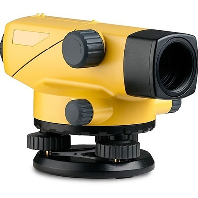
Any and all measurement processes will contain errors. In the case of levelling, these errors will be (1) instrumental, (2) observational and (3) natural.
Instrumental errors
- The main source of instrumental error is residual collimation error. As already indicated, keeping the horizontal lengths of the backsights and foresights at each instrument position equal will cancel this error. Where the observational distances are unequal, the error will be proportional to the difference in distances. The easiest approach to equalizing the sight distances is to pace from backsight to instrument and then set up the foresight change point the same number of paces away from the instrument.
- Parallax error
- Staff graduation errors may result from wear and tear or repairs and should be checked against a steel tape. Zero error of the staff, caused by excessive wear of the base, will cancel out on backsight and foresight differences. However, if two staffs are used, errors will result unless calibration corrections are applied.
- In the case of the tripod, loose wing nuts will cause twisting and movement of the tripod head. Overtight wing nuts make it difficult to open out the tripod correctly. Loose tripod shoes will also result in unstable set-ups
SURVEYING MADE EASY GATE NOTES : CLICK HERE
Observational errors
- Since the basic concept of levelling involves vertical measurements relative to a horizontal plane, careful staff holding to ensure its verticality is fundamentally important. Rocking the staff back and forth in the direction of the line of sight and accepting the minimum reading as the truly vertical one is frequently recommended. However, this concept is incorrect when using a flat-bottomed staff on flat ground, due to the fact that it is not being tilted about its face. Thus it is preferable to use a staff bubble, which should be frequently checked with the aid of a plumb-bob.
- Errors in reading the staff, particularly when using a tilting level which gives an inverted image. These errors may result from inexperience, poor observation conditions or overlong sights. Limit the length of sight to about 25–30 m, thereby ensuring clearly defined graduations.
- Ensure that the staff is correctly extended or assembled. In the case of extending staffs, listen for the click of the spring joint and check the face of the staff to ensure continuity of readings. This also applies to the jointed staff.
- Moving the staff off the CP position, particularly when turning it to face the new instrument position. Always use a well-defined and stable position for CPs. Levelling plates should be used on soft ground
- Similarly with the tripod. To avoid tripod settlement, which may alter the height of collimation between sights or tilt the line of sight, set up on firm ground, with the tripod feet firmly thrust well into the ground. Even on pavements, locate the tripod shoes in existing cracks or joins.
- In precise levelling, the use of two staffs helps to reduce this effect. Beginners should also refrain from touching or leaning on the tripod during observation.
- Booking errors can, of course, ruin good field work. Neat, clear, correct booking of field data is essential in any surveying operation. Typical booking errors in levelling are entering the values in the wrong columns or on the wrong lines, transposing figures such as 3.538 and 3.583 and making arithmetical errors in the reduction process. Very often, the use of pocket calculators simply enables the booker to make the errors quicker. To avoid this error source, use neat, legible figures; read the booked value back to the observer and have him check the staff reading again; reduce the data as it is recorded.
- When using a tilting level remember to level the tubular bubble with the tilting screw prior to each new staff reading. With the automatic level, carefully centre the circular bubble and make sure the compensator is not sticking. Residual compensator errors are counteracted by centring the circular bubble with the instrument pointing backwards at the first instrument set-up and forward at the next. This procedure is continued throughout the levelling
SURVEYING ACE GATE NOTES : CLICK HERE
Natural errors
- Curvature and refraction have already been dealt with. Their effects are minimized by equal observation distances to backsight and foresight at each set-up and readings not less then 0.5 m above the ground.
- Wind can result in unsteady staff holding and instrument vibration. Precise levelling is impossible in strong winds. In tertiary levelling keep the staff to its shortest length and use a wind break to shelter the instrument.
- Heat shimmer can make staff reading difficult if not impossible and may result in delaying the work to an overcast day. In hot sunny climes, carry out the work early in the morning or evening. Careful consideration of the above error sources, combined with regularly calibrated equipment, will ensure the best possible results but will never preclude random errors of observation.
ENGINEERING SURVEYING TEXTBOOK BY CIVILENGGFORALL PDF
DOWNLOAD LINK : CLICK HERE
PASSWORD : CivilEnggForAll
OTHER USEFUL BOOKS
- RAJASTHAN STAFF SELECTION BOARD (RSSB) JUNIOR ENGINEER DIPLOMA CIVIL ENGINEERING EXAM 2022 – HINDI & ENGLISH MEDIUM SOLVED PAPER – FREE DOWNLOAD PDF (CivilEnggForAll.com)
- ISRO TECHNICAL ASSISTANT EXAM 2022 – CIVIL ENGINEERING – HINDI & ENGLISH MEDIUM – SOLVED PAPER – FREE DOWNLOAD PDF (CivilEnggForAll.com)
- MADHYA PRADESH PUBLIC SERVICE (MPPSC) COMMISSION – ASSISTANT ENGINEER EXAM – MPPSC AE 2021 CIVIL ENGINEERING – SOLVED PAPER WITH EXPLANATIONS – PDF FREE DOWNLOAD
- BIHAR PUBLIC SERVICE COMMISSION (BPSC) ASSISTANT ENGINEER EXAM – 2022 – CIVIL ENGINEERING – SOLVED PAPER – FREE DOWNLOAD PDF (CivilEnggForAll.com)
- ODISHA PUBLIC SERVICE COMMISSION – OPSC AEE PANCHAYATI RAJ EXAM 2021 – SOLVED PAPER WITH EXPLANATION – FREE DOWNLOAD PDF