
CONTENTS
- Public Water Supply Scheme
- Water Demand
- Per Capita Demand
- Population Forecasts
- Safe or Firm Yield
- Hydrological Cycle
- Precipitation
- Rainfall
- Index of Wetness
- Run–OFF
- Sources of Water
- Intake for Collecting Surface Water
- Conduits for Transporting Water
- Flows in Pipe Systems
- Analysis of Complex Pipe Networks
- Pumps for Lifting Water
- Quality Control of Municipal and Industrial Water
- Analysis of Water
- Water Quality Standards
- Water Borne Diseases and Their Control
- Methods of Purification of Water
- Coagulation Sedimentation Plant
- Coagulant Quantities
- Forms in Which Chlorine Can be Applied
- Distribution of Water
- Storage Reservoirs

PUBLIC WATER SUPPLY SCHEME
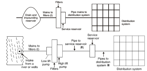
- Suitable systems should be designed for collecting, transporting, and treating water.
- In case of dams and reservoirs, dumping are not required.
- In case a river is used as a source, pumping equipment is required
Design periods
It is the future period or the number of years for which a provision is made in designing capacities of the various components of the water supply scheme. Water supply projects, under normal circumstances, may be designed for a design period of 30 years. This 30 years is to be counted after completion of the project.
Essential Elements
- Intake and reservoir: To collect water.
- Water treatment plant: It includes screening, sedimentations, filtration, disinfection units etc.
- Elevated tanks and Stand pipes: It provide storage to meet peak demands occurring for limited periods.
- Valves: It control flow of water in the pipe system.
- Hydrants: It provide a connection with the water in the main for fighting fires, flushing streets etc.
- Distribution system: It includes mains, submains, and branch lines which carry the water to the streets.
- Service: It carry the water to the individual house etc.
WATER DEMAND
Types of Water Demands
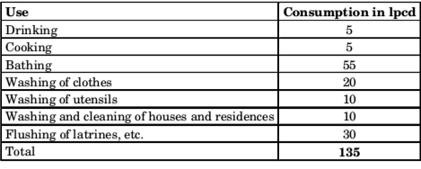
1. Domestic Water Demand (55 to 60% of total water consumption) – As per IS 1172-1983 as well as National building code, domestic consumption under normal conditions in an Indian city is expected to be around 135 lpcd (litres/capita/day)
2. Industrial Water Demand (50 lpcd) – Ordinary per capita consumption for industrial needs of a city is generally taken as 50 lpcd
3. Institutional and Commercial Water Demand (20 lpcd) – On an average, per capita demand of 20 lpcd is usually considered to be enough to meet such water requirements, although this demand may be as high as 50 lpcd for highly commercialised cities.
4. Demand for Public uses (10 lpcd)
5. Fire Demand (1 lpcd) Fire hydrants are usually fitted in the water mains at about 100 to 150 metres apart. Thus per capita fire demand is generally ignored while computing total per capita water requirement of a city. When population exceeding 50,000, kilo litre of water required = 100√P where, P = population in thousand.
6. Wastes and Thefts etc (55 lpcd) – Even in best managed water works, this amounts to be 15% of total water consumption.
IES MASTER CIVIL ENGINEERING GATE STUDY MATERIALS PDF: DOWNLOAD LINK
ACE ACADEMY CIVIL ENGINEERING GATE STUDY MATERIALS PDF: DOWNLOAD LINK
SOURCES OF WATER
Classification of Sources of Water
Surface sources
- Ponds and Lakes – If size of the depression is comparatively small, it is called pond, and when size of depression is larger, it is called lake. Due to smaller quantity of water available from them, lakes are not considered as principal source of water supplies.
- Streams and Rivers – Small stream channels feed their waters to the lakes or rivers. Rivers are most important sources of water supply schemes. Types of Rivers:
(a) Perennial rivers: Water is available throughout the year.
(b) Non-perennial rivers: Quality of water obtained from these rivers is not reliable.
- Storage Reservoirs – A water supply scheme drawing water directly from a river or a stream may fail to satisfy the consumers demands during extremely low flows. To avoid such problem a dam is constructed across a river for storage of water. The artificial lake is formed on the upstream side is called storage reservoir.
- Ocean, generally not used for water supplies
Selection of a particular Source of Water depends on following factors:
- Quantity of available water
- Quality of available water
- Distance of the source of supply
- General topography of the intervening area
- Elevation of the source of supply
Subsurface or Underground Sources
- By Natural process: In springs, ground water is brought to the surface by some natural processes.
- By Artificial process: In wells, tube wells, infiltration galleries etc, the water is tapped by artificial means. .
- Spring
- Infiltration galleries
- Infiltration wells
- Wells and tube-wells.
Geological Factors Governing Occurrence of Underground Water
Following two properties of the underground soil affect occurring of water:
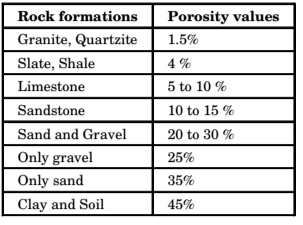
1. Porosity of the soil: It is defined as maximum amount of water that can be stored in the rock. This porosity, however, in itself, does not ensure storage of underground water, because water can enter into a rock only if rock permits flow of water through it. A rock which is porous, may or may not be permeable.
2. Permeability and Transmissibility of the Soil -Capability of the entire soil of full width and depth is represented by permeability; while that of the soil of unit width and full depth is called transmissibility. Permeability is measured in terms of coefficient of permeability.
ACE ACADEMY CIVIL ENGINEERING GATE HANDWRITTEN CLASSROOM NOTES PDF: DOWNLOAD LINK
MADE EASY CIVIL ENGINEERING GATE HANDWRITTEN CLASSROOM NOTES PDF: DOWNLOAD LINK
INTAKE FOR COLLECTING SURFACE WATER
Basic function of intake structure is to help in safely withdrawing water from the source over a predetermined range of pool levels and then to discharge this water into the withdrawal conduit through which it flows upto the water treatment plant.
Site Selection of Intake
It depends on following factors
- Availability of water is all seasons
- Quality and quantity of water
- Away from the pollution
- Nearer to the city
- Upstream side of the river
- Costs and reliability
Types of Intakes
1. Simple submerged Intake
These intakes are not used on bigger projects on river and reservoir because they are not easily accessible for cleaning, repairing, etc.
2. Intake Towers
These are of following two types:
- Wet intake towers
- Dry intake towers – These are standing in the river or reservoir
The essential difference between these two is that, in a wet intake tower, water enters from the entry ports into the tower and then it enters into the conduit pipe through separate gate controlled opening; but in a dry intake tower, water is directly drawn into the withdrawal conduit through the gated entry ports.
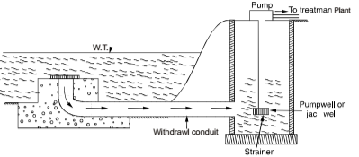
3. Medium sized Intake wells (River Intake)
(i) Medium sized River Intake – Water from the intake chamber is taken through a withdrawal conduit (called intake conduit) to a sump well, from where it is lifted and taken to the treatment plant.
(ii) Canal Intake Well
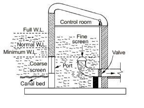
- Entry of water in the intake well takes through a coarse screen, the top of which is generally provided at minimum water level in the canal, and bottom is about 0.45 m above the canal bed to avoid entry of bed load.
- An additions fine screen is provided at the inlet end of the withdrawal conduit. This inlet end of bell mouth shape with perforation of fine screen on its surface.
- An outlet value, operating from the top, is provided to control entry of water into the outlet pipe.
- Flow velocity through the outlet conduit is generally kept as about 1.5 m/sec., and this helps in determining area and diameter of the withdrawal conduit.
- Area of the coarse screen is designed by limiting flow velocity to as low as 0.15 m/ sec or so. Flow velocity through the bell mouth inlet is limited to about 0.3 m/sec or so.
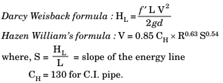
Head loss in the intake conduit upto treatment works, can be determined by using following formulae:
4. Intake for Sluiceways of Dam
In case a reservoir developed by constructing a dam, it is a common practice to fetch water through the sluiceways from inside the dam. In case of earthen dams, intake for withdrawing water into the sluiceway of the dam, is generally located near the upstream toe of the dam. whereas for masonry dam, intake well for withdrawing water is generally located inside the body of the dam. The arrangement is similar to that of a dry intake tower, only different that it was surrounded by water on all sides and was standing in the river, whereas this valve tower is fed through conduits and is standing in the dam or very near the dam.
ENVIRONMENTAL ENGINEERING IES MASTER GATE STUDY MATERIAL PDF: DOWNLOAD LINK
ENVIRONMENTAL ENGINEERING ACE ACADEMY GATE STUDY MATERIAL PDF: DOWNLOAD LINK
CHEMICAL IMPURITIES IN WATER, THEIR CAUSES AND EFFECTS

Bacteriological Impurities
These are caused by the presence in water of the pathogenic or disease producing type of bacteria making water dangerous for human consumption and health. From the public health point of view, therefore, bacteriological impurities are the most important. Types of parasitic Organisms Infective to man Found in Water
Bacteria
These are minute single cell organisms possessing no defined nucleus and having no green material to help them manufacture their own food. They are reproduced by binary fission and may be of various shapes, and sizes are 1 to 4 microns, examined by microscope.
There are two types of Bacteria:
- Non-disease causing Bacteria: Non pathogenic
bacteria.
- Disease causing Bacteria: Pathogenic bacteria.
Classification of Bacteria based on Oxygen requirements.
- Aerobic Bacteria: These require oxygen for their survival.
- Anaerobic Bacteria: These flourish in the absence of free oxygen.
- Facultative Bacteria: These can survive with or without free oxygen.
Pathogenic bacteria
These can be tested and counted in the laboratories but with great difficulty. Thus these are generally not performed in routine to check up of the water quality. The usual routine tests are generally conducted to detect and count the presence of coliforms which in themselves are harmless organisms, but their presence or absence indicates presence or absence of pathogenic bacteria.
Methods to measure presence of Coliform Bacteria
- Membrane filter technique (Modern technique).
- Mixing different dilution of a sample of water with lactose froth and incubating them in test- tubes for 48 hours at 370C. The presence of acid or carbon dioxide gas in tubes will indicates presence of coliform bacteria. Most probable number (MPN) represent bacterial density.
- Coliform Index. It may be defined as reciprocal of the smallest quantity of a sample which would give a positive portion. Coliform sometimes, called Bacteria coli (B– coli) or Escherichia coli (E-coli) are harmless aerobic micro-organisms.
Other types of impurities include Protozoa (These are single cell animals and are lowest and the simplest form of animal life. These are bacteria eaters and thus destroy Pathogens. They are directly counted by microscope), Viruses, Worms, Fungus
ENVIRONMENTAL ENGINEERING ACE ACADEMY GATE CLASSROOM NOTES PDF: DOWNLOAD LINK
ENVIRONMENTAL ENGINEERING MADE EASY GATE CLASSROOM NOTES PDF: DOWNLOAD LINK
ANALYSIS OF WATER
Physical Analysis of Water
Turbidity
It is measured by a turbidity rod or by a turbidimeter with optical observations, and is expressed as amount of suspended matter in mg/l or parts per million (ppm). For water, ppm and mg/l are approximately equal. The standard unit is that which is produced by one milligram of finely divided silica (Fuller’s earth) in one litre of distilled water.
Turbidimeters
- Turbidity Rod: Used to measure turbidity in the field. It consists of an aluminium rod which is graduated, as to give the turbidity directly in silica units (mg l.)
- Turbidimeter: Used to measure turbidity in the laboratory. In general, it works on the principle of measuring interference caused by the water sample to the passage of light rays.
- Jackson’s Candle Turbidimeter: Used to measure natural source only, and it cannot be used to measure turbidities of treated supplies, for which Baylis’s turbidimeter or modern nephelometers are used.
- Baylis’s Turbidimeters: One of the two glass tubes is filled with water sample (whose turbidity is to be measured) and the other is filled with standard water solution of known turbidity. The electric bulb is lighted and the blue colour in both the tubes is observed from the top of the instrument.
- Modern Nephelometer: Used to measure low turbidity less than 1 unit NTU — Nephelometric Turbidity Units FTU — Formazin Turbidity Units
- Ratio Turbidimeter: Used to measure turbidity of river water, which has maximum amount of turbidity.
Colour
Presence of colour in the water is not objectionable from health point of view; but may spoil colour of the clothes being washed. The standard unit of colour is that which is produced by one milligram of platinum cobalt dissolved in one litre of distilled water. For public supplies, colour number on cobalt scale should not exceed 20, and should be preferably be less than 10. Colour determined by an instrument called tintometer.
Taste and Odour
The extent of taste or odour present in a particular sample of water is measured by a term called odour intensity, which is related with the threshold odour or threshold odour number. Thus water to be tested is gradually diluted with odour free water, and mixture at which detection of odour by human observation is just lost, is determined. The number of times, sample is diluted, represents threshold odour number. For public supplies, water should generally free from odour, i.e. threshold number should be 1 and should never exceed 3.
Temperature – For potable waters, temperature of about 10°C are highly desirable° It should not be more than 250C.
Specific conductivity – Total amount of dissolved salts present in water can be easily estimated by measuring specific conductivity of water.
WATER SUPPLY CIVIL ENGINEERING GATE 2020 STUDY MATERIAL FREE DOWNLOAD PDF
DOWNLOAD LINK : CLICK HERE
PASSWORD : CivilEnggForAll
OTHER USEFUL BOOKS
- CIVIL ENGINEERING TEXTBOOKS WITH DOWNLOAD LINKS
- IES MASTER CIVIL ENGINEERING GATE STUDY MATERIALS PDF
- ACE ACADEMY CIVIL ENGINEERING GATE STUDY MATERIALS PDF
- RAJASTHAN STAFF SELECTION BOARD (RSSB) JUNIOR ENGINEER DIPLOMA CIVIL ENGINEERING EXAM 2022 – HINDI & ENGLISH MEDIUM SOLVED PAPER – FREE DOWNLOAD PDF (CivilEnggForAll.com)
- ISRO TECHNICAL ASSISTANT EXAM 2022 – CIVIL ENGINEERING – HINDI & ENGLISH MEDIUM – SOLVED PAPER – FREE DOWNLOAD PDF (CivilEnggForAll.com)
- MADHYA PRADESH PUBLIC SERVICE (MPPSC) COMMISSION – ASSISTANT ENGINEER EXAM – MPPSC AE 2021 CIVIL ENGINEERING – SOLVED PAPER WITH EXPLANATIONS – PDF FREE DOWNLOAD
- BIHAR PUBLIC SERVICE COMMISSION (BPSC) ASSISTANT ENGINEER EXAM – 2022 – CIVIL ENGINEERING – SOLVED PAPER – FREE DOWNLOAD PDF (CivilEnggForAll.com)
- ODISHA PUBLIC SERVICE COMMISSION – OPSC AEE PANCHAYATI RAJ EXAM 2021 – SOLVED PAPER WITH EXPLANATION – FREE DOWNLOAD PDF