
CONTENTS
- Highways
- Highway Geometric Design
- Sight Distance
- PIEV Theory
- Design of Horizontal Alignment
- Design of Vertical Alignment
- Highway Material
- Testing and Specification of Paving
- Materials
- Tests on Road Aggregates
- Bituminous Materials
- Tar
- Cement
- Standard Tests
- Design of Highway Pavements
- Design of Rigid Pavements
- Traffic Parameters
- Environmental Parameters
- Foundation Strength
- Foundation Surface Characteristics
- Concrete Characteristic Pavement
- Modulus of Elasticity (E) and Poisson’s Ratio
- Coefficient of Thermal Expansion
- Design of Slab Thickness
- Calculation of Stresses
- Design of Joints
- Design of Dowel Bars
- Geometrical Design of Railway Track
- Radius of Curve/Degree of Curve (D°)
- Versine of Curve
- Super Elevation (Cant)
- Equilibrium Cant (for Equilibrium Speed)
- Cant Deficiency (D)
- Runaway Length
- Balanced Field Concept
- Taxiway
- Exit Taxiway
- Traffic Engineering
Note – This book covers the theoretical part of Transportation Engineering. Examples, solved problems, solutions and explanations will be covered in Part-2
SIGHT DISTANCE
It is length of road visible ahead to the driver at any instance. Three sight distance situations are considered in the design:
Stopping Sight Distance (SSD) – Minimum sight distance available on a highway at any instant or spot should be of sufficient length to stop a vehicle travelling at design speed, safely without collision with any other obstruction. It is also called absolute minimum sight distance or non-passing sight distance.
Factors affecting Sight distance available on road to a driver at any instant
- Feature of the road ahead
- Height of the driver’s eye above the road surface
- Height of the object above the road surface.
IRC has suggested the height of eye level of driver as 1.2 m and height of the object as 0.15 m above the road surface. Hence stopping distance available at a curve is that distance measured along the road surface at which an object of height 0.15 m can be seen by a driver whose eye is at a height of 1.2m above the road surface.
Distance within which a motor vehicle can be stopped
It depends on following factors:
- Total reaction time of the driver
- Speed of the vehicle
- Efficiency of brakes: To avoid skid, braking force or frictional force
- Frictional resistance between the road and the tyres and
- Gradient of the road if any.
Total Reaction Time – Total reaction time of the driver is the time taken from the instant the object is visible to the driver to the instant the brakes are effectively applied. Total reaction time may be split up into following two parts:
- Perception time: It is the time required for a driver to realise that brake must be applied.
- Brake reaction time
IES MASTER CIVIL ENGINEERING GATE STUDY MATERIALS PDF: DOWNLOAD LINK
ACE ACADEMY CIVIL ENGINEERING GATE STUDY MATERIALS PDF: DOWNLOAD LINK
HIGHWAY MATERIAL
Sub-Grade Soil
The main function of sub-grade is to give adequate support to the pavement.
Desirable Properties of soil as a Highway material
- Stability
- Incompressibility
- Permanency of strength
- Minimum changes in volume and stability under adverse conditions of weather and ground water
- Good discharge
- Ease of compaction.
Group Index of Soil
In order to classify fine grained soils within a group and for judging their suitability as subgrade material, an indexing system has been introduced in HRB classification which is called group index. G. I = 0.2a + 0.005 ac + 0.01 bd
Here,
- a = portion of material passing 0.074 mm sieve, greater than 35 and not exceeding 75%.
- b = portion of material passing 0.074mm sieve greater than 15 and not exceeding 35%
- c = value of liquid limit in excess of 40 and less than 60.
- d = value of plasticity index exceeding 10 and not more than 30.
The value of group index lies between zero and 20. Higher the value of group index, poorer is the soil as subgrade material.
Factors affecting Strength characteristics of Soil
- Soil type
- Moisture content
- Dry density
- Internal structure of the soil
- Type and mass of stress application.
TESTING AND SPECIFICATION OF PAVING MATERIALS
Construction Materials for Roads
- Soil
- Aggregate
- Bituminous materials
- Cement concrete
SOIL
It is an integral part of the pavement structure which provides support to the pavement from beneath. The main function is to given adequate support to the pavement and for this the subgrade should possess sufficient stability under adverse climate and loading conditions. Poor subgrade causes wave corrugation, rutting and shoving in black top pavements and phenomenon of pumping, blowing and consequent cracking of cement concrete pavements.
Required Properties of Soil
- Stability
- Incompressibility
- Permanency of strength
- Minimum changes in volume and stability under adverse conditions of weather ground water
- Good drainage
- Ease of compaction.
AGGREGATES
It can be defined as inert material fragments and particles forming main structure of a mixture such as tarmacadam or concrete and is the basic material for road construction. This material forms greater part of the body of the road and bears mains stresses occurring in the road and resists wear from surface abrasion. The particles are bound together by bituminous materials or cement which act as binders and develop a strong structure forming the crust of the road. Properties of sub-materials should be known by a highway engineer for the formation of roads or pavements.
Desirable Properties of Road Aggregates
- Hardness: It is a measure of its resistance to crushing and abrasion at the surface.
- Toughness: It is a property that enables them to resist any friction when subjected to impact due to moving vehicles.
- Durability: It determines life span of the road.
- Cementitious value: Cementitious property comes from ability of the road stone to form its own binding material under traffic so as to make the rough broken stone pieces grip together, imparting resistance to displacement.
- Adhesion with bitumen
List of Tests on Road Aggregates
- Crushing test
- Abrasion test
- Impact test
- Soundness test
- Shape test
- Bitumen adhesion test
- Specific gravity & water absorption test
ACE ACADEMY CIVIL ENGINEERING GATE HANDWRITTEN CLASSROOM NOTES PDF: DOWNLOAD LINK
MADE EASY CIVIL ENGINEERING GATE HANDWRITTEN CLASSROOM NOTES PDF: DOWNLOAD LINK
Attrition Test
This test determine percentage of wear of the given broken stone sample. This is a combined test for determining suitability of stone for hardness and toughness. When Deval abrasion test is carried out by Deval machine without using abrasive changes, the test is known as ‘Deval – Attrition test’.
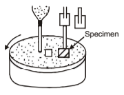
Apparatus
Deval’s attrition testing machine, a balance and I.S. sieve of size 1.7 mm. Specimen This test is conducted for rock specimens as well as gravel specimens. The equipment consists of a pair of a hollow iron cylinders of internal diameter 200 mm and length 340 mm. Cylinders are fixed to a frame, which in turn is connected to a shaft that is rotated by means of a motor at a rate of 30 revolutions per minutes. Cylinders are inclined to the horizontal axis at an angle of 30. If gravel is to be tested, it s hall consist of uncrushed fragments. Sample of the material shall first be separated into different sizes, washed and dried before mixing them to form the required grading. Total weight of the sample shall be 5 kg when dry.
Procedure
- Put 5 kg of sample in both the cylinders of Deval’s Attrition testing machine and close the cylinders (W1 g)
- Allow the cylinders to rotate 10,000 revolution at the rate of 30 revolutions per minute.
- After 10,000 revolutions take out the contents from the cylinders and sieve through a sieve of 1.7 mm aperture.
- Weight the quantity of material retained on the sieve. (W2 g)
- Calculate percentage of wear as: Percentage of wear = Loss in weight/Initial weight x 100 = (W1-W2)/W1 x 100
Inference: If wear is more than 3 per cent, stone is not satisfactory. If it is equal to 3 percent stone is just tolerable. For a good stone, wear should be equal to or less than 2 per cent.
Los Angele’s Abrasion Test
This test is carried out on crushed rock, crushed slag, uncrushed gravel and crushed gravel.
Inference: The Los Angles abrasion value of good aggregates acceptable for cement concrete, bituminous concrete, and other high quality pavements should be less than 30%. For W.B.M & bituminous macadam it may be upto 50%.
Apparatus: Machine consist of a cylindrical drum 70 cm in diameter and 50 cm long on the inside mounted on two pivots at the ends and capable of rotation horizontally. An opening for the full length is provided in the cylinder for charging the material into it (opening can be covered with the help of a lid). A removable steel shelf, projecting radially 8.6 cm into the cylinder and extending to its full length is mounted rigidly inside the cylinder. Position of fixing the shelf is such that distance measured from this to the edge of the opening along the inside circumference in the direction of rotation is not less than 125 cm. No 12 A.S.T.M. sieve (1.7 mm) is needed to sieve the material after the test, in addition to the sieves needed to prepare test samples.
Test sample: It consists of clean aggregate which has been dried in an oven to substantially constant weight conforming to one the grading.
Procedure
- Test sample is placed in the Los Angele’s machine and along with it are fed the abrasive charge consisting of steel balls. The number of balls to be fed is 12 in the case of gradings A, E, F, and G, 11 in case of B, 8 in case of C and 6 case of D. Average weight of each ball is 417 gms, size of the ball being 4.76 cm.
- Machine is rotated at in speed of 30 to 33 revolutions per minute. Number of revolutions to be given is 500 in the case of gradings. A, B, C and D and shall be 1,000 in the case of gradings E,F and G.
- Material is taken out and sieved on No.12 (1.7 mm) sieve. Material coarser than this size is washed, dried in an oven at a temperature of 1050C to 1100C to a constant weight. Difference between this weight and the original weight is expressed as percentage loss over the original weight. This is taken as index of wear for the material.
TRANSPORTATION ENGINEERING ACE ACADEMY GATE NOTES PDF: CLICK HERE
TRANSPORTATION ENGINEERING MADE EASY GATE NOTES PDF: CLICK HERE
Dorry’s Abrasion Test
This test is carried out to determine coefficient of hardness of the given sample.
Apparatus: Dorry’s abrasion testing machine and a Balance. The machine consists of a cast steel case which revolves in a horizontal plane about a vertical shaft. A suitable attachment exists for holding the specimen with its axis vertical and its lower end pressed with a prescribed pressure against the surface of the disc. The distance form center of the specimen to the center of the shaft is 260 mm. A convenient funnel for feeding the abrasive size (size 425 microns) continuously on the disc at predetermined rate is provided. If rock specimen has to be tested, it is ground in the form of cylinder of 25.40 mm diameter and 25.40 mm long. Surface at right angles to the axis of the cylinder is plane and it is pressed against the revolving disc of the machine with a weight of 1250 g. Then disc should be rotated for 1000 revolutions at a speed of 28 revolutions per minute. If gravel specimen has to be tested, the material is placed in these pockets covered with steel plates and pressed against the disc with a weight of 2000 g. Then disc should be rotated for 500 revolutions at a speed of 28 revolutions per minute.
Procedure
- Take a cylindrical specimen of diameter 25.40 mm and height 25.40 and weight it (W1 g)
- Place the specimen in Dorry’s testing machine and press it with a pressure of 1250 g
- Rotate annular steel disc of the machine at a speed of 28 revolutions per minute.
- During rotation of disc, sprinkle coarse sand of standard specification on top of the two tests.
- After 1000 revolutions, take out the specimen and weight it (W2 g)
- Repeat the test with the specimen reversed and compute average loss of weight from the two tests.
- Calculate coefficient of hardness as: Coefficients of hardness = 20 – Loss in weighting/3 = (W-W2)/3 grams
Note: Hardness of 17 indicates a good stone, a value between 14 to 17 indicates medium quality stone and below 14 indicates unsuitability of stone for road work.
Crushing Strength Test
This test is carried out to determine crushing value of the given aggregate. This test indicates suitability of aggregate for concrete and also gives a measure of aggregate quality
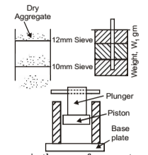
Apparatus
- Mould unit consisting of an open ended steel cylinder, with plunger and base plate.
- Tamping rod (45 – 60 cm long)
- Balance.
- I.S. sieve of size 12.5 mm, 10 mm (I.S. sieve No 240.)
- Compression testing machine.
In case of rock specimens, the result is expressed as crushing strength whereas in the case of aggregate, the result is expressed as percentage of fines formed. For the rock specimen, compression testing machine shall be needed along with spherical seatings to ensure loading. In case of test for aggregate, mould consist of an open ended steel cylinder of internal dimensions 152 mm diameter and 130 to 140 mm height with a closely fitting ram or a plunger of diameter 150 mm. The cylinder rest on a smooth steel plate. Tamping rod is a straight metal rod 16 mm in diameter and 600 mm long.
Procedure
- Take 5 kg of aggregates (W1 g)
- Fill the cylinder with aggregates in three equal layers and compact each layer by giving 25 strokes with tamping rod.
- Fill the cylinder with aggregates in three equal layers and compact each layer by giving 25 strokes with tamping rod.
- Level top surface of the aggregates and then insert the plunger. Now top edge of the plunger flange coincides exactly with top of the cylinder.
- Collect the aggregate left over on the sides of the mould and weight the excess aggregate (W2 g). Then find weight of aggregate in the cylinder (W1 – W2) g
- Place the apparatus carefully in a compression testing machine and apply a load of 10 tonnes for a period of 10 minutes. Then release the load.
- Sieve the crushed material with I.S. sieve No. 240. Take care to avoid loss of fines. Weigh the fraction passing through the sieve (W3 g).
- Repeat the experiment once again using same weight of fresh aggregates (W1 – W2) g.
- Calculate crushing value of aggregates: Crushing value = 100 x (weight of aggregate passing through the sieve) / (weight of aggregate taken in the cylinder) = W3/(W1-W2) x 100
Note: Crushing value for base course should not exceed 45% and for wearing surfaces it should not exceed 30%.
TRANSPORTATION ENGINEERING PART-1 CIVIL ENGINEERING GATE 2020 STUDY MATERIAL FREE DOWNLOAD PDF
DOWNLOAD LINK : CLICK HERE
PASSWORD : CivilEnggForAll
OTHER USEFUL BOOKS
- CIVIL ENGINEERING TEXTBOOKS WITH DOWNLOAD LINKS
- IES MASTER CIVIL ENGINEERING GATE STUDY MATERIALS PDF
- ACE ACADEMY CIVIL ENGINEERING GATE STUDY MATERIALS PDF
- RAJASTHAN STAFF SELECTION BOARD (RSSB) JUNIOR ENGINEER DIPLOMA CIVIL ENGINEERING EXAM 2022 – HINDI & ENGLISH MEDIUM SOLVED PAPER – FREE DOWNLOAD PDF (CivilEnggForAll.com)
- ISRO TECHNICAL ASSISTANT EXAM 2022 – CIVIL ENGINEERING – HINDI & ENGLISH MEDIUM – SOLVED PAPER – FREE DOWNLOAD PDF (CivilEnggForAll.com)
- MADHYA PRADESH PUBLIC SERVICE (MPPSC) COMMISSION – ASSISTANT ENGINEER EXAM – MPPSC AE 2021 CIVIL ENGINEERING – SOLVED PAPER WITH EXPLANATIONS – PDF FREE DOWNLOAD
- BIHAR PUBLIC SERVICE COMMISSION (BPSC) ASSISTANT ENGINEER EXAM – 2022 – CIVIL ENGINEERING – SOLVED PAPER – FREE DOWNLOAD PDF (CivilEnggForAll.com)
- ODISHA PUBLIC SERVICE COMMISSION – OPSC AEE PANCHAYATI RAJ EXAM 2021 – SOLVED PAPER WITH EXPLANATION – FREE DOWNLOAD PDF