
CONTENTS
- System of Forces
- Equilibrium Equations
- Internal Forces in Structures
- Principle of Transmissibility
- Varignon’s Theorem
- Couple
- Friction
- Self Locking Mechanism
- Kinematics
- Centre of Mass
- Centroid of Different Figures
- Euler’s Equation of Motion
- Impulse-Momentum
- Conservation of Linear Momentum
- Angular Impulse and Angular Momentum
- Energy Methods
- Potential Energy

SYSTEM OF FORCES
Force is the action of one body on another. A force tends to move a body in the direction of its action. The action of a force is characterized by its magnitude, by the direction of its action, and by its point of application. Thus, force is a vector quantity.
Different Types of Force Systems
Collinear Forces – In this system, line of action of all the forces act along the same line
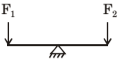
Coplanar parallel force: In this system, all forces are parallel to each other and lie in a single plane.
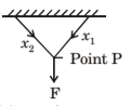
Coplanar concurrent point: In this system, line of action of all forces passes through a single point and forces lie in the same plane.
Coplanar non-concurrent forces – All forces do not meet at a point but lie in a single plane.
Non-coplanar parallel forces – In this system all the forces are parallel to each other but not in the same plane.
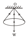
Non-coplanar concurrent forces –In this system, all forces do not lie in the same plane but their line of action passes through a single point.
One system is in which, all forces do not lie in the same plane and their lines of action do not pass through a single point; they may not be parallel.
IES MASTER CIVIL ENGINEERING GATE STUDY MATERIALS PDF: CLICK HERE
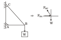
Free-Body Diagrams
In applying the principles of mechanics to analyse forces acting on a body, it is essential to isolate the body in question from all other bodies so that a complete and accurate amount of all forces acting on this body can be taken. The diagram of such an isolated body with the representation of all external forces acting on it is called a free-body diagram.
Three Force Theorem – If three forces are acting on a body and then the system of three forces is in equilibrium, must be coplanar, and either be concurrent or be parallel – that is a three force theorem.
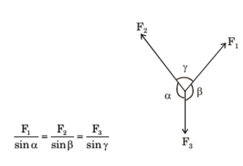
Lami ’s Theorem
When three coplanar and concurrent forces acting on a body are kept in equilibrium, then each force is proportional to the sine of the angle between the other two and the constant of proportionality is the same
The forces acting on a body are of two types:
- External Forces: These forces on structures are the stresses that act on a structure from outside. For example: gravity force, impact force
- Internal Forces: These forces act between different parts of the same structure. Internal forces are of four types: tension, compression, torsion and shear.
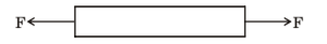
Tension Force – The force which causes all of the particles of an object to pull apart is called tension.
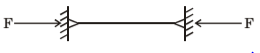
Compression Force – The force that presses or squeezes the particles of an object together is known as compression.
Torsion Force
The internal twisting forces created in an object as a result of a twisting motion being applied to the object is known as torsion.
Shear Force
The forces acting in an object as a result of pushes and/or pulls in opposite directions; usually results in rips or tears in an object is known shear.
ACE ACADEMY CIVIL ENGINEERING GATE STUDY MATERIALS PDF: CLICK HERE
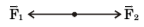
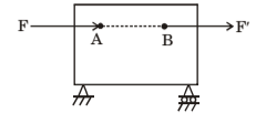
Principle of Transmissibility
The principle of transmissibility states that a force may be applied at any point on its given line of action without altering the resultant effects of the force external to the rigid body on which it acts. For example: The two forces F and F’ have the same effect on the rigid body and are said to be equivalent.
Varignon’s Theorem
This theorem states that moment of a force about any point is equal to the sum of the moments of the components of that force about the same point i.e. the moment about a given point O of the resultant of several concurrent forces is equal to the sum of the moments of the particular forces about the same point
r x F1 + r x F2 + …. = r x (F1 + F2 + ….)

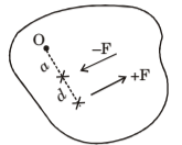
Couple
The moment produced by two equal, opposite and noncollinear forces is called a couple. For example: If two equal and opposite forces F and – F are d distance – F +F O a d apart as shown in Fig. These two forces cannot be combined into a single forces because there sum in every direction is zero. Their only effect is to produce a tendency of rotation. The combined moment of the tow forces about an axis normal to their plane is the couple M.
M = F(a+d) – Fa = Fd
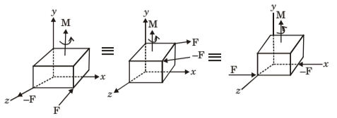
Equivalent Couples
The two couples producing the same moment M are equivalent.
- The two couples are lie in the parallel plane
- The two couples have the same sense or the tendency to cause rotation in the same direction. A couple is not affected if the forces act in a different but parallel plane, as shown in Figure
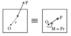
Force-Couple System
Any force acting on a rigid body may be moved to an arbitrary point O, provided that a couple is added, of moment equal to the moment of F about O and the combination obtained is referred to as a force-couple system.
MADE EASY CIVIL ENGINEERING GATE NOTES PDF: CLICK HERE
FRICTION
When a body slides over another body, a resisting force is exerted at the surface of contact by stationary body on the moving body, this is called the frictional force.
Characteristics of Friction
Considering a block resting on a horizontal plane with irregularities at the mating surface, this rough and irregular surface would cause degree of unlocking and wedging action between the mating surface. When tractive force P is applied to the block in parallel to contact surface, a resisting force F would be generated automatically opposite to applied direction of P.
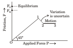
Following are the features of frictional (Figure):
- During static condition, i.e. block is at rest, with increase in applied force P, F will increase showing the relationship of direct proportionality. This can be shown in region 0-1, known as zone of static friction (Fig.) and point 1 is known as mass static friction.
- When block is set into motion and frictional force cannot be increased further, at that situation F is called as limiting friction. This is maximum friction force at time of impending motion (motion is about to begin).
- After certain point, friction force starts dropping to lower value called kinetic friction. Zone 2-3 is zone of kinetic friction (Fig.)
Hence, the main characteristics of friction force can be summarized as:
- Always acts in the direction opposite to applied motion.
- By nature it is passive force and will sustain as long as tractive force will be in action.
- Self adjusting force.
Nature of Friction
- Dry Friction (Coloumb friction): This comes into action when contact surfaces are dry. This is further divided into two parts: Sliding force and Rolling force.
- Fluid Friction: This comes into action when lubricating fluid is intended between contact surfaces.
- Static and Dynamic Friction Static friction develops when no relative motion exists between contacting surfaces Dynamic friction develops when there is relative motion between contacting surfaces.
Laws of Solid Friction
- Friction acts tangential to contact surfaces and always in opposite direction of applied motion.
- Friction force is maximum at the time motion is about to begin and vary from zero to maximum.
- Limiting friction is independent of area and shape of contact surfaces.
- Limiting friction depends upon nature of contact surfaces (being rough or smooth)
ENGINEERING MECHANICS CIVIL ENGINEERING GATE 2020 STUDY MATERIAL FREE DOWNLOAD PDF
DOWNLOAD LINK : CLICK HERE
PASSWORD : CivilEnggForAll
OTHER USEFUL BOOKS
- RAJASTHAN STAFF SELECTION BOARD (RSSB) JUNIOR ENGINEER DIPLOMA CIVIL ENGINEERING EXAM 2022 – HINDI & ENGLISH MEDIUM SOLVED PAPER – FREE DOWNLOAD PDF (CivilEnggForAll.com)
- ISRO TECHNICAL ASSISTANT EXAM 2022 – CIVIL ENGINEERING – HINDI & ENGLISH MEDIUM – SOLVED PAPER – FREE DOWNLOAD PDF (CivilEnggForAll.com)
- MADHYA PRADESH PUBLIC SERVICE (MPPSC) COMMISSION – ASSISTANT ENGINEER EXAM – MPPSC AE 2021 CIVIL ENGINEERING – SOLVED PAPER WITH EXPLANATIONS – PDF FREE DOWNLOAD
- BIHAR PUBLIC SERVICE COMMISSION (BPSC) ASSISTANT ENGINEER EXAM – 2022 – CIVIL ENGINEERING – SOLVED PAPER – FREE DOWNLOAD PDF (CivilEnggForAll.com)
- ODISHA PUBLIC SERVICE COMMISSION – OPSC AEE PANCHAYATI RAJ EXAM 2021 – SOLVED PAPER WITH EXPLANATION – FREE DOWNLOAD PDF