
CONTENTS
- DIRECT AND BENDING STRESSES
- DEFLECTION OF BEAMS
- METHODS TO FIND SLOPE AND DEFLECTION
- DOUBLE INTEGRATION METHOD
- MACAULAY’S METHOD
- AREA-MOMENT METHOD
- CONJUGATE BEAMS METHOD
- PROPERTIES OF AREA
- MOMENT DISTRIBUTION METHOD
- FIXED END MOMENTS
- THEORY OF COLUMN ANALOGY

DIRECT AND BENDING STRESSES
When a structure is loaded, work is done on the structure. The work done is transformed either partially or completely in the form of potential energy referred to as strain energy of internal energy. If the strain produced remains within elastic limit, the potential energy of strain can be recovered on unloading of the structure. The strain energy in a structure may be due to direct stresses, shear stresses, and bending stresses. In care of beams and frames, the strain energy due to direct and shear stress is very small in comparison to strain energy due to bending stresses. Therefore, the strain energy due to direct and shear stresses, is generally neglected while finding the indeterminate reactions, and moments in beams and frames. However, in the find checks the effect of direct and shear stresses may be taken into account.
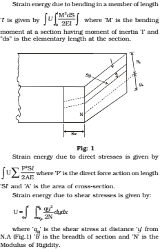
In reality, the method of strain energy is a force method, wherein redundant reaction forces or moments are determined at the very beginning. The method use the theorem of least work which states that for any statically indeterminate structure, the redundants should be such as to make the total strain energy within the structure a minimum. The validity of the theorem of least works comes directly from costigiliano’s second theorem which may be stated as follows. The partial derivative of the total internal energy in a beam, with respect to the load applied at any point, is equal to the deflection at that point. For externally redundant structures, if the support do not yield, the work done by the loads is stored up as strain energy will be minimum. However, if the supports yield some work is also done on supports. In such cases total work done will consist of strain energy stored in the structure plus the work done is to be minimum, the sum of strain energy stored in the structure plus work done on supports will be minimum.
THEORY OF STRUCTURES IES MASTER GATE STUDY MATERIAL PDF : CLICK HERE
Conjugate Beam Method (Given by Mohr)
It is applicable for prismatic & non prismatic both. It can be applied for beams containing internal hinges and also Conjugate Beam is an imaginary beam for which loading diagram is M/EI diagram curvature diagram) of given beam. The end condition & support conditions are modified such that slope & deflection in given beam is represented by shear force & B.M respective in conjugate Beam. If given real beam is stable & determine then conjugate beam is also stable & determine, but if given beam is indeterminate then conjugate beam is unstable & if given beam is unstable then conjugate beam is indeterminate.
- Theorem 1: “ The slope at any point in the given beam is equal to shear force at that point in the conjugate beam. It Means S.F.D of conjugate beam represents slope curve of given beam.
- Theorem 2: “ The deflection at any point in the given beam is equal to B.M point in the conjugate beam. It means MD of conjugate Beam represents deflection curve/ elastic curve of given beam.
GUIDELINES TO DRAW CONJUGATE BEAM
- Diagram of given beam is loading diagram of conjugate beam. If B.M.D of given beam is (+ve) (sagging) then loading in conjugate Beam will be upward & if BMD in given beam (–ve) hogging then loading in conjugate beam will be downward.
- If S.F at any beam in conjugate beam is (+ve) then slope at that point is given beam is also (+ve) (anticlockwise) & vice-versa.
- If B.M at any point in conjugate Beam is (+ve) (sagging) then deflection an actual beam at that point is (+ve) upward & if BM is hogging (–ve) then deflection in given beam is downwards.
- The support condition will be modified in such a way if given beam has slope then at that point conjugate beam should have S.F & if given beam has deflection then conjugate Beam should have Given Real Beam conditions.
THEORY OF STRUCTURES ACE GATE STUDY MATERIAL PDF : CLICK HERE
MOMENTS DISTRIBUTION METHOD
Analysis of indeterminate beams and frames by the methods of strain energy and slope deflection involves solving a number of simultaneous equation which is tedious and time consuming. The moment distribution method is a displacement method of analysis that is easy to apply once certain elastic constants have been determined. Essentially it is a method to solve the simultaneous equations in the slope-deflection method by successive approximations, accurate to as many significant figure as desired.
In fact this method sidesteps the calculation of the displacements and instead make it possible to apply a series of converging corrections that allow direct calculation of the end moments.
STRUCTURAL ANALYSIS ACE GATE NOTES PDF : CLICK HERE
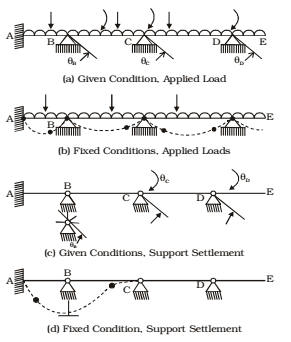
Basic Concept and Definition:
The deformation response of a continuous beam or a rigid frame without unknown joint translation is completely defined by the unknown joint rotations, such as TB, TC and TD in physically, it is conceivable, that locking moment can be applied to joint ‘B’, ‘C’ and ‘D’. So the method begins by assuming each joint of structure is fixed (locked joint). Then by unlocking and locking each joint in succession, the internal moment at joints are distributed and balanced until the joints have routed to their final or nearly final value. In fact, the magnitude of these locking moments are known in advance in terms of the applied loads or the support settlements. When the locking moment at one of the joint is released, that joint will rotate. This rotation induces changes not only in the movements at the member ends entering the released joint, but also in the locking moments at the immediately adjacent joints on both sides of the released joint. If each joint is successively released and locked back and then this process is repeated, a time will be reached at which every point joint has attained its full needed value in the final deformation response. Then the locking moment would have dissipated, or distributed throughout the structure by means of successive amount of joint rotations. Sign Convention: Clockwise moments at the fixed joints of a loaded and clockwise moments acting at the member ends are considered positive
THEORY OF STRUCTURES STUDY MATERIAL FOR RRB JE PDF CIVILENGGFORALL
DOWNLOAD LINK : CLICK HERE
PASSWORD : CivilEnggForAll
OTHER USEFUL BOOKS
- RAJASTHAN STAFF SELECTION BOARD (RSSB) JUNIOR ENGINEER DIPLOMA CIVIL ENGINEERING EXAM 2022 – HINDI & ENGLISH MEDIUM SOLVED PAPER – FREE DOWNLOAD PDF (CivilEnggForAll.com)
- ISRO TECHNICAL ASSISTANT EXAM 2022 – CIVIL ENGINEERING – HINDI & ENGLISH MEDIUM – SOLVED PAPER – FREE DOWNLOAD PDF (CivilEnggForAll.com)
- MADHYA PRADESH PUBLIC SERVICE (MPPSC) COMMISSION – ASSISTANT ENGINEER EXAM – MPPSC AE 2021 CIVIL ENGINEERING – SOLVED PAPER WITH EXPLANATIONS – PDF FREE DOWNLOAD
- BIHAR PUBLIC SERVICE COMMISSION (BPSC) ASSISTANT ENGINEER EXAM – 2022 – CIVIL ENGINEERING – SOLVED PAPER – FREE DOWNLOAD PDF (CivilEnggForAll.com)
- ODISHA PUBLIC SERVICE COMMISSION – OPSC AEE PANCHAYATI RAJ EXAM 2021 – SOLVED PAPER WITH EXPLANATION – FREE DOWNLOAD PDF