
TOPICS COVERED
INTRODUCTION TO STRUCTURAL ANALYSIS AND LOADS
- Introduction to Structural Analysis
- Loads on Structures
ANALYSIS OF STATICALLY DETERMINATE STRUCTURES
- Equilibrium and Support Reactions
- Planes and Space Trusses
- Beams and Frames – Shear Force and Bending Moment
- Deflections of Beams – Geometric Methods
- Deflections of Trusses, Beams and Frames – Work-Energy Methods
- Influence Lines
- Application of Influence Lines
- Analysis of Symmetric Structures
ANALYSIS OF STATICALLY INDETERMINATE STRUCTURES
- Introduction to Statically Indeterminate Structures
- Approximate Analysis of Rectangular Building Frames
- Method of Consistent Deformations – Force Method
- Three-Moment Equation and the Method of Least Work
- Influence Lines for Statically Indeterminate Structures
- Slope-Deflection Method
- Moment-Distribution Method
- Introduction to Matrix Structural Analysis

INTRODUCTION AND HISTORY OF STRUCTURAL ANALYSIS
Structural analysis is the prediction of the performance of a given structure under prescribed loads and/or other external effects, such as support movements and temperature changes. The performance characteristics commonly of interest in the design of structures are (1) stresses or stress resultants, such as axial forces, shear forces, and bending moments; (2) deflections; and (3) support reactions. Thus, the analysis of a structure usually involves determination of these quantities as caused by a given loading condition. Since the dawn of history, structural engineering has been an essential part of human endeavour. However, it was not until about the middle of the seventeenth century that engineers began applying the knowledge of mechanics (mathematics and science) in designing structures. Earlier engineering structures were designed by trial and error and by using rules of thumb based on past experience. The fact that some of the magnificent structures from earlier eras, such as Egyptian pyramids (about 3000 b.c.), Greek temples (500–200 b.c.), Roman coliseums and aqueducts (200 b.c.–a.d. 200), and Gothic cathedrals (a.d. 1000–1500), still stand today is a testimonial to the ingenuity of their builders. Galileo Galilei (1564–1642) is generally considered to be the originator of the theory of structures. In his book entitled Two New Sciences, which was published in 1638, Galileo analysed the failure of some simple structures, including cantilever beams. Although Galileo’s predictions of strengths of beams were only approximate, his work laid the foundation for future developments in the theory of structures and ushered in a new era of structural engineering, in which the analytical principles of mechanics and strength of materials would have a major influence on the design of structures. Following Galileo’s pioneering work, the knowledge of structural mechanics advanced at a rapid pace in the second half of the seventeenth century and into the eighteenth century. Among the notable investigators of that period were Robert Hooke (1635–1703), who developed the law of linear relationships between the force and deformation of materials (Hooke’s law); Sir Isaac Newton (1642–1727), who formulated the laws of motion and developed calculus; John Bernoulli (1667– 1748), who formulated the principle of virtual work; Leonhard Euler (1707–1783), who developed the theory of buckling of columns; and C. A. de Coulomb (1736–1806), who presented the analysis of bending of elastic beams. In 1826 L. M. Navier (1785–1836) published a treatise on elastic behaviour of structures, which is considered to be the first textbook on the modern theory of strength of materials. The development of structural mechanics continued at a tremendous pace throughout the rest of the nineteenth century and into the first half of the twentieth, when most of the classical methods for the analysis of structures described in this text were developed.
The important contributors of this period included B. P. Clapeyron (1799–1864), who formulated the three-moment equation for the analysis of continuous beams; J. C. Maxwell (1831–1879), who presented the method of consistent deformations and the law of reciprocal deflections; Otto Mohr (1835–1918), who developed the conjugate-beam method for calculation of deflections and Mohr’s circles of stress and strain; Alberto Castigliano (1847–1884), who formulated the theorem of least work; C. E. Greene (1842–1903), who developed the moment-area method; H. Muller-Breslau (1851–1925), who presented a principle for constructing influence lines; G. A. Maney (1888– 1947), who developed the slope-deflection method, which is considered to be the precursor of the matrix stiffness method; and Hardy Cross (1885–1959), who developed the moment-distribution method in 1924. The moment-distribution method provided engineers with a simple iterative procedure for analyzing highly statically indeterminate structures. This method, which was the most widely used by structural engineers during the period from about 1930 to 1970, contributed significantly to their understanding of the behaviour of statically indeterminate frames. Many structures designed during that period, such as high-rise buildings, would not have been possible without the availability of the moment distribution method. The availability of computers in the 1950s revolutionized structural analysis. Because the computer could solve large systems of simultaneous equations, analyses that took days and sometimes weeks in the pre computer era could now be performed in seconds. The development of the current computer-oriented methods of structural analysis can be attributed to, among others, J. H.Argyris, R. W. Clough, S. Kelsey,R. K. Livesley, H. C. Martin, M. T. Turner, E. L. Wilson, and O. C. Zienkiewicz.
STRUCTURAL ANALYSIS IES MASTER GATE MATERIAL : CLICK HERE
ROLE OF STRUCTURAL ANALYSIS IN STRUCTURAL ENGINEERING PROJECTS
Structural engineering is the science and art of planning, designing, and constructing safe and economical structures that will serve their intended purposes. Structural analysis is an integral part of any structural engineering project, its function being the prediction of the performance of the proposed structure. As this diagram indicates, the process is an iterative one, and it generally consists of the following steps:
1. Planning Phase – The planning phase usually involves the establishment of the functional requirements of the proposed structure, the general layout and dimensions of the structure, consideration of the possible types of structures (e.g., rigid frame or truss) that may be feasible and the types of materials to be used (e.g., structural steel or reinforced concrete). This phase may also involve consideration of non-structural factors, such as aesthetics, environmental impact of the structure, and so on. The outcome of this phase is usually a structural system that meets the functional requirements and is expected to be the most economical. This phase is perhaps the most crucial one of the entire project and requires experience and knowledge of construction practices in addition to a thorough understanding of the behaviour of structures.
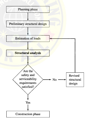
2. Preliminary Structural Design – In the preliminary structural design phase, the sizes of the various members of the structural system selected in the planning phase are estimated based on approximate analysis, past experience, and code requirements. The member sizes thus selected are used in the next phase to estimate the weight of the structure.
3. Estimation of Loads – Estimation of loads involves determination of all the loads that can be expected to act on the structure.
4. Structural Analysis – In structural analysis, the values of the loads are used to carry out an analysis of the structure in order to determine the stresses or stress resultants in the members and the deflections at various points of the structure.
5. Safety and Serviceability – Checks The results of the analysis are used to determine whether or not the structure satisfies the safety and serviceability requirements of the design codes. If these requirements are satisfied, then the design drawings and the construction specifications are prepared, and the construction phase begins.
6. Revised Structural – Design If the code requirements are not satisfied, then the member sizes are revised, and phases 3 through 5 are repeated until all the safety and serviceability requirements are satisfied.
STRUCTURAL ANALYSIS ACE GATE STUDY MATERIAL : CLICK HERE
CLASSIFICATION OF STRUCTURES
Commonly used structures can be classified into five basic categories, depending on the type of primary stresses that may develop in their members under major design loads. However, it should be realized that any two or more of the basic structural types described in the following may be combined in a single structure, such as a building or a bridge, to meet the structure’s functional requirements.
Tension Structures
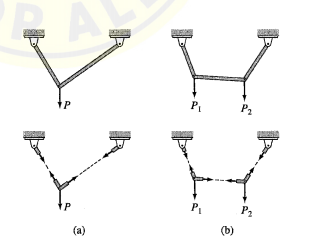
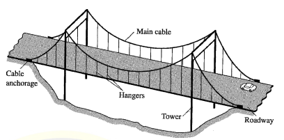
The members of tension structures are subjected to pure tension under the action of external loads. Because the tensile stress is distributed uniformly over the cross-sectional areas of members, the material of such a structure is utilized in the most efficient manner. Tension structures composed of flexible steel cables are frequently employed to support bridges and long-span roofs. Because of their flexibility, cables have negligible bending stiffness and can develop only tension. Thus, under external loads, a cable adopts a shape that enables it to support the load by tensile forces alone. In other words, the shape of a cable changes as the loads acting on it change. In a suspension bridge, the roadway is suspended from two main cables by means of vertical hangers. The main cables pass over a pair of towers and are anchored into solid rock or a concrete foundation at their ends. Because suspension bridges and other cable structures lack stiffness in lateral directions, they are susceptible to wind-induced oscillations. Bracing or stiffening systems are therefore provided to reduce such oscillations. Besides cable structures, other examples of tension structures include vertical rods used as hangers (for example, to support balconies or tanks) and membrane structures such as tents.
STRUCTURAL ANALYSIS MADE EASY GATE NOTES : CLICK HERE
Compression Structures
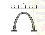
Compression structures develop mainly compressive stresses under the action of external loads. Two common examples of such structures are columns and arches. Columns are straight members subjected to axially compressive loads. When a straight member is subjected to lateral loads and/or moments in addition to axial loads, it is called a beam-column. An arch is a curved structure, with a shape similar to that of an inverted cable. Such structures are frequently used to support bridges and long-span roofs. Arches develop mainly compressive stresses when subjected to loads and are usually designed so that they will develop only compression under a major design loading. However, because arches are rigid and cannot change their shapes as can cables, other loading conditions usually produce secondary bending and shear stresses in these structures, which, if significant, should be considered in their designs. Because compression structures are susceptible to buckling or instability, the possibility of such a failure should be considered in their designs; if necessary, adequate bracing must be provided to avoid such failures.
Trusses
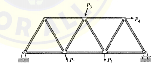
Trusses are composed of straight members connected at their ends by hinged connections to form a stable configuration. When the loads are applied to a truss only at the joints, its members either elongate or shorten. Thus, the members of an ideal truss are always either in uniform tension or in uniform compression. Real trusses are usually constructed by connecting members to gusset plates by bolted or welded connections. Although the rigid joints thus formed cause some bending in the members of a truss when it is loaded, in most cases such secondary bending stresses are small, and the assumption of hinged joints yields satisfactory designs. Trusses, because of their light weight and high strength, are among the most commonly used types of structures. Such structures are used in a variety of applications, ranging from supporting roofs of buildings to serving as support structures in space stations.
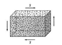
Shear Structures
Shear structures, such as reinforced concrete shear walls, are used in multi-storey buildings to reduce lateral movements due to wind loads and earthquake excitations. Shear structures develop mainly in plane shear, with relatively small bending stresses under the action of external loads
Bending Structures
Bending structures develop mainly bending stresses under the action of external loads. In some structures, the shear stresses associated with the changes in bending moments may also be significant and should be considered in their designs. Some of the most commonly used structures, such as beams, rigid frames, slabs, and plates, can be classified as bending structures. A beam is a straight member that is loaded perpendicular to its longitudinal axis. Recall from previous courses on statics and mechanics of materials that the bending (normal) stress varies linearly over the depth of a beam from the maximum compressive stress at the fiber farthest from the neutral axis on the concave side of the bent beam to the maximum tensile stress at the outermost fiber on the convex side. For example, in the case of a horizontal beam subjected to a vertically downward load, the bending stress varies from the maximum compressive stress at the top edge to the maximum tensile stress at the bottom edge of the beam. To utilize the material of a beam cross section most efficiently under this varying stress distribution, the cross sections of beams are often I-shaped, with most of the material in the top and bottom flanges.
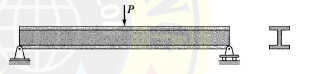
The I-shaped cross sections are most effective in resisting bending moments. Rigid frames are composed of straight members connected together either by rigid (moment-resisting) connections or by hinged connections to form stable configurations. Unlike trusses, which are subjected only to joint loads, the external loads on frames may be applied on the members as well as on the joints. The members of a rigid frame are, in general, subjected to bending moment, shear, and axial compression or tension under the action of external loads. However, the design of horizontal members or beams of rectangular frames is often governed by bending and shear stresses only, since the axial forces in such members are usually small. Frames, like trusses, are among the most commonly used types of structures. Structural steel and reinforced concrete frames are commonly used in multistorey buildings, bridges, and industrial plants. Frames are also used as supporting structures in airplanes, ships, aerospace vehicles, and other aerospace and mechanical applications.
STRUCTURAL ANALYSIS TEXTBOOK BY CIVILENGGFORALL PDF
DOWNLOAD LINK : CLICK HERE
PASSWORD : CivilEnggForAll
STRUCTURAL ANALYSIS TEXTBOOKS LIST WITH DOWNLOAD LINKS : CLICK HERE
OTHER CIVIL ENGINEERING TEXTBOOKS WITH DOWNLOAD LINKS : CLICK HERE
OTHER USEFUL BOOKS
- RAJASTHAN STAFF SELECTION BOARD (RSSB) JUNIOR ENGINEER DIPLOMA CIVIL ENGINEERING EXAM 2022 – HINDI & ENGLISH MEDIUM SOLVED PAPER – FREE DOWNLOAD PDF (CivilEnggForAll.com)
- ISRO TECHNICAL ASSISTANT EXAM 2022 – CIVIL ENGINEERING – HINDI & ENGLISH MEDIUM – SOLVED PAPER – FREE DOWNLOAD PDF (CivilEnggForAll.com)
- MADHYA PRADESH PUBLIC SERVICE (MPPSC) COMMISSION – ASSISTANT ENGINEER EXAM – MPPSC AE 2021 CIVIL ENGINEERING – SOLVED PAPER WITH EXPLANATIONS – PDF FREE DOWNLOAD
- BIHAR PUBLIC SERVICE COMMISSION (BPSC) ASSISTANT ENGINEER EXAM – 2022 – CIVIL ENGINEERING – SOLVED PAPER – FREE DOWNLOAD PDF (CivilEnggForAll.com)
- ODISHA PUBLIC SERVICE COMMISSION – OPSC AEE PANCHAYATI RAJ EXAM 2021 – SOLVED PAPER WITH EXPLANATION – FREE DOWNLOAD PDF