AUTOCAD BASICS
INTERFACE – TOOLBARS – COMMANDS
AutoCAD Basic Commands explanation and steps to use the commands
AutoCAD Basic Commands explanation and steps to use the commands in detail, which every Civil Engineer and students needs to know.
What is AutoCAD?
AutoCAD, created by Autodesk, is the most widely used technical drawing program anywhere, with more than 3 million registered users. According to Autodesk, CAD stands for computer-aided design, but can also stand for computer aided drafting or drawing. The first version of AutoCAD, running under DOS, came out in 1982. AutoCAD was the first significant CAD program to run on a desktop computer. At the time, most other technical drawing programs ran on high-end workstations or even mainframes. AutoCAD’s success has been attributed to its famous open architecture—many source code files in plain text (ASCII) files that you can easily customize and programming languages (such as AutoLISP and Visual Basic for Applications) designed especially so that the end user can program AutoCAD. As a result, AutoCAD is the most flexible drafting program available, applicable to all fields. AutoCAD’s support for languages other than English, including those using other alphabets, is unparalleled, making AutoCAD without serious competition abroad. As a result, AutoCAD is used in all disciplines and in more than 150 countries.
TOPICS COVERED IN THIS TUTORIAL
- AutoCAD Interface
- Draw Commands
- Line command
- Polygon command
- Rectangle command
- Circle command
- Ellipse commands
- Edit Commands
- Erase command
- Copy command
- Mirror command
- Offset command
- Extend command
- Array command
- Move command
- Rotate command
- Scale command
- Trim command
- Chamfer command
- Fillet command
AUTOCAD Interface
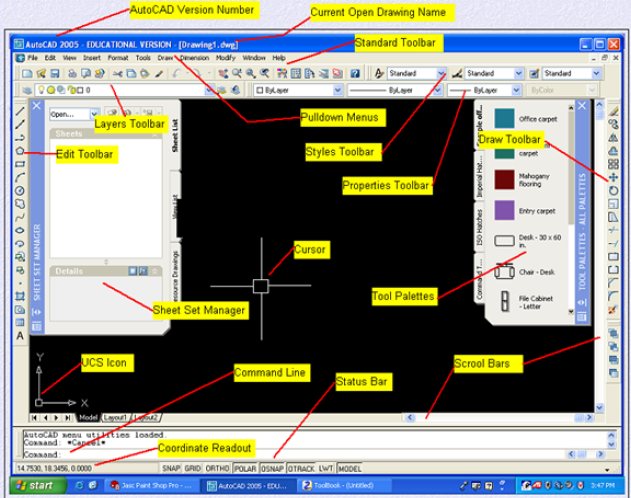
AutoCAD Version Number : Shows which AutoCAD Version you are running on.
Current Open Drawing Name : Shows the name of the drawing you currently have open
Standard Toolbar : Toolbar for standard AutoCAD Commands
Pulldown Menus : Easy access to AutoCAD Commands
Layers Toolbar : Access AutoCAD Layer commands
Edit Toolbar : Access to AutoCAD editing commands
Styles Toolbar : Access AutoCAD Styles toolbar
Properties Toolbar : Access properties toolbar
Cursor : Used to point to objects in AutoCAD
Draw Toolbar : Access to AutoCAD draw commands
Tool Palettes : Access to tool pallettes
Scroll Bars : Used to scroll around drawing in drawing area
Status Bar : Used to turn on and off AutoCAD settings
Command Line : Used to type in AutoCAD commands from keyboard
Coordinate Readout : Used to keep track of cursor location in drawing area
Sheet Set Manager : Access sheet set manager
AutoCAD Basic Commands explanation and steps to use the commands
LEARN AUTOCAD ONLINE – COMMANDS
DRAW COMMAND
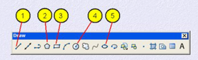
Draw toolbar is used to access AutoCAD Draw commands. You can also use draw pulldown menu or type the command in at the command line. The draw commands create objects such as lines, circles and ellipses. An object is the smallest component of a drawing. A drawing is made up of a combination of these objects. When creating objects with draw commands, AutoCAD always prompts “Ask” you to indicate points (such as end points, centers, or radii) to describe the size and location of the object to be drawn. Drawing commands can be entered from the keyboard (command line), the Draw Toolbar or the Draw Pull-down menu.
1. Line : Draw lines in AutoCAD
2. Polygon : Draws polygons with three or more sides
3. Rectangle : Used to draw rectangles
4. Circle : Command used to draw circles
5. Ellipse : Used to draw ellipse
LINE COMMAND
Line Command is use to draw lines in AutoCAD. Steps to use Line Command are as follows.
1. Press F8 on keyboard to turn on ORTHO
2. Click on the LINE icon in the draw toolbar
3. Specify first point. Pick any point on your screen with the mouse
4. Move your cursor to the right a little do not click down
5. Type in : 2 (Press Enter)
6. Move your cursor up a little do not click down
7. Type in : 2 (Press Enter)
8. Move your cursor to the left a little do not click down
8. Type in : 2 (Press Enter)
9. Move your cursor down a little do not click down
10. Type in : 2 (Press Enter)
You should have drawn a perfect Square box !
1. Click on LINE icon
2. Specify first point : Pick any point on your screen with the mouse
3. Move your cursor to the right a little do no click down
4. Type in : 2 (Press Enter)
5. Press F8 on the keyboard to turn off ORTHO
6. Specify next point : Pick point 2 with your mouse
7. Type in : C (Press Enter)
You should have created something that resembles a triangle.
POLYGON COMMAND
Command use to draw a polygon with three or more sides
1. Draw two circles of any diameter using the circle icon. (Refer to the circle command if you do not know how to use this command)
2. Click on the POLYGON icon in the draw toolbar
3. Enter number of sides at this point you can enter as many sides as you wish (No less than three sides) At this time type in 8 (press enter)
4. Specify center of polygon type in CEN (press enter)
5. Move your cursor around the outer edge of one of the circles until you see a small yellow circle at the center of the bigger circle. Hold the cursor there until the word CENTER appears then click down with the mouse
6. Enter the option type, type in c (Press Enter)
7. Specify radius of circle type in NEAR (Press Enter)
8. Move the cursor to the outer edge of the circle hold it there until you see a small yellow hour glass and the word NEAREST appears then click down with the mouse. You may put a polygon within a circle (Inscribed) by typing in, in step 6 an “I” instead of a “c”
RECTANGLE COMMAND
Command used to draw a rectangle
1. Click on the RECTANGLE icon in the draw toolbar
2. Specify first corner point : click anywhere on your screen
3. Specify other corner, move your cursor up and to the right any distance you wish then click down. If you wish to draw a rectangle a specific size, follow the below steps.
1. Repeat steps 1 and 2
2. Specify other corner type in @3,1 (press enter)
Using this option you have entered a specific length and height for your polygon. You may change the numbers to anything you wish but leave the @ and the, in its exact location. Broken down the 3 is the length and 1 is the height. The @ symbol tells AutoCAD that you are using relative co-ordinate entry.
CIRCLE COMMAND
Command used to draw circles
1. Click on the CIRCLE icon in the draw toolbar. 2. Specify center point of circle click anywhere in the drawing area.
3. Specify the radius of circle Type in 25 (press enter)
To draw a circle by specifying a circle diameter do the following
1. Repeat steps 1 and 2
2. Specify radius of circle Type in D (Press enter)D stands for diameter
3. Specify diameter of circle Type in 1 (Press enter)
To draw a circle at the intersection of two lines 1. Draw two lines that overlap using the line command
2. Click on the CIRCLE in the draw toolbar
3. Specify center point of circle Type in INT (press enter)
4. Move your cursor to the intersection of two lines until you see a small yellow X and the word INTERSECTION
5. Now you can either type in a radius or type in D for diameter and move on the next prompt to type in the diameter.
ELLIPSE COMMAND
Command used to draw ellipses
1. Click on the ELLIPSE icon in the draw toolbar 2. Specify axis endpoint. Click anywhere on your Screen
3. Specify other endpoint. Pick another point a distance you specify to the right of first point you picked. This will be the major axis of your ellipse
4. Move your cursor up a distance you specify and click. This will be your minor axis.
To draw an ellipse with a center, rotation,and angle do the following
1. Repeat step 1 above.
2. Specify axis endpoint of ellipse Type in: C (press enter)
3. Specify center of ellipse. Pick anywhere in the drawing area
4. Specify the endpoint of axis. move your cursor to the right a little then type in: .50 (press enter) You have entered the radius of the circle you are trying to make an ellipse from. The radius of the circle is all that is needed
5. Specify distance to other axis Type in R (press enter)
6. Specify rotation around major axis Type in 30 (press enter) You have entered the rotation angle of the line of sight of the ellipse. For example if you were looking at an ellipse at a 30 degree angle, the rotation would be 30 degrees
MODIFY TOOLBAR
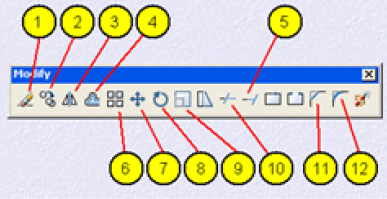
Modify toolbar is used to access AutoCAD Draw commands can also Modify pulldown menu or type the command in at the Command line. After you have created some objects in AutoCAD, objects that make up a technical drawing such as lines and circles or a combination of both, they are sometimes just not the way you would like them, they may need to be rotated, moved, copied, scaled larger or smaller, etc. To do these things you need to have a good basic understanding of some of the AutoCAD editing commands.
In this module these are 12 of the most basic AutoCAD editing commands.With these 12 commands you can do 90 percent of most editing operations. Practice these 12 commands learn them well. The best way to access these commands is by using the editing toolbar at the right of the AutoCAD opening screen.
1. Erase – Erase object in the drawing area
2. Copy – Used to copy one or more objects
3. Mirror – Command used to mirror an exact duplicate of an object.
4 Offset – Used to offset one object from another a distance you specify
5. Extend – Used to extend one line to another
6. Array – Use to make a rectangular or polar array of an object
7. Move – Used to move objects around in the drawing area
8.Rotate – Used to rotate an object around a base point
9. Scale – Command used to make an object larger or smaller
10. Trim – Command used to trim an object from another object
11. Chamfer – Used to put a chamfer between two lines
12. Fillet – Used to put a fillet between two lines of a radius you specify
ERASE COMMAND
Command used to erase objects in the drawing area
1. Draw a line and a circle of any length any diameter
2. Click on the ERASE icon in the edit toolbar
3. Select objects : Select all objects that you would like to erase with the pick box. When you are done selecting objects press ENTER on keyboard. The objects should disappear.
COPY COMMAND
Command used to copy objects in the drawing area
1. Draw a circle any diameter.
2. Click on the COPY icon in the edit toolbar.
3. Select objects : Select the circle with the pick box (on the line) when the circle is highlighted press the ENTER key on the keyboard.
4. Select objects : 1 found (This line ask you if you would like to select more objects if not press ENTER on the keyboard).
5. Specify base point of displacement : Pick with the near the center of the circle
6. Move the object to the location you desire and click down with the mouse.
MIRROR COMMAND
Command used to mirror an object to the side of another object
1.Draw a rectangle any size using the rectangle command
2. Click the MIRROR icon in the edit toolbar
3. Select objects : Select the rectangle with the pick box (on the line)
4. Select objects : Press ENTER on the keyboard 5. Specify point on mirror line : Move your cursor to the right and above a short distance from the rectangle. Click down with the mouse. 6. Specify first point of mirror line : Specify second point of mirror line: move your cursor down a short distance then click down with the mouse
7. Delete source objects Type in : N (Press enter) An exact duplicate of the rectangle you created in step 2 will be created to the right Note: If you create a mirror line above the rectangle an exact duplicate of the rectangle will be created above. You can mirror any object in the drawing area text, lines, circles, views, etc.
OFFSET COMMAND
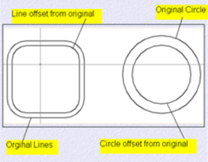
Command used to offset one object from another
1. Draw a circle and a line of any diameter any length
2. Click on the OFFSET icon in the edit toolbar. 3. Specify offset distance Type int: .50 (press enter)
4. Select object to offset Select the line with the pick box.
5. Specify point on side to offset: Pick just above the line you have selected in step 4 with the cursor. An exact duplicate of the first line you selected in step 4 is created just above .50 distance away. If you would have picked the line you in step an exact duplicate be created .50 below.
6. Select object to offset press ENTER on the keyboard. You can offset almost any object in the drawing area. You can offset text. You can also offset a circle to the inside or outside itself. To offset inside a circle click inside the circle. To offset outside the circle click outside the circle
EXTEND COMMAND
Command used to extend one line to another
1. Draw two lines one horizontal and one vertical. Draw the vertical line a short distance away from the horizontal line.
2. Click on the EXTEND icon in the edit toolbar. 3. Select boundary edges. Select objects the vertical line (the line you want to extend to).
4. Press ENTER on the keyboard
5. Select objects to extend Select the right end point of the horizontal line with the pick box. The horizontal line will now extend to the vertical line.
6. Press the ESC key on the keyboard to cancel the command.
ARRAY COMMAND
How to do a rectangular array
1. Start a new drawing from scratch.
2. Draw a polygon, 6 sides, inscribed, with a radius of .50
3. Click on the ARRAY icon in the edit toolbar The array dialog box opens
4. Set ROWS to 6, set COLUMNS to 6.
5. Set ROW OFFSET to 1.5 set COLUMNS OFFSET to 1.50
6. Click on SELECT OBJECTS icon.
7. Select the polygon with the pick box (on the line) Then press ENTER on the keyboard
8. Click on OK
Note: The row and offset distance is taken from the center of the polygon
How to do a polar array
1. Draw two circles diameter
2. Click on the ARRAY icon The array dialog box opens
3. Click on POLAR ARRAY
4. Click on SELECT OBJECTS icon Click on the small circle (on the line) then press ENTER on the keyboard.
5. Click on the PICK CENTER POINT icon Type in CEN (press enter), Move the curs over to the large circle (on the line) when a small circle appears at its centre click down with the mouse 6. Set TOTAL NUMBER OF ITEMS to 6, set ANGLE TO FILL to 360
7. Click on OK. 6 small circles should appear around the larger circle.
SCALE COMMAND
Command used to scale an object larger or smaller in size
1. Draw circle of any diameter
2. Click on the SCALE icon in the edit toolbar
3. Select objects : Select the circle (on the Iine) then press ENTER on the keyboard
4. Specify base point : Click near the center of the circle with the cursor.
5. Specify scale factor or reference: Type in 2 press enter on the keyboard. This makes the circle 2 times its original size if you were to type in 50 it would make the circle-half its original size. This can be done with any object created the AutoCAD drawing area a percentage less than 1 makes the object smaller A percentage more than 1 makes the object bigger. A percentage of 1 has know effect on the object.
MOVE COMMAND
Command used to move an object from one location to another in the drawing area
1. Draw a circle of any diameter
2. Click on the MOVE icon in the edit toolbar
3. Select objects : Select the circle (on the line) then press ENTER on the keyboard
4. Specify basepoint of displacement Select near the center of the circle with the cursor.
5. Specify second point of displacement. If you move your cursor around little in the drawing area you can see what is called rubberbanding 6. Click down the mouse anywhere within the drawing area at the desired location for the move.
ROTATE COMMAND
Command used rotate an object around a point you pick
1. Draw a rectangle with only two equal sides rectangle command
2. Click on the ROTATE icon in the edit toolbar
3. Select objects : Select the rectangle (on the line) then press ENTER on the keyboard
4. Specify base point select somewhere near the center of the rectangle with the cursor.
5. Specify rotation angle At this point you can type in an angle of rotation at the command line or by moving your mouse around you can dynamically see the rotation angle, then click down with the mouse when you like the rotation angle.
TRIM COMMAND
Command used to trim one line back from another line
1. Draw two overlapping line one horizontal and one vertical
2. Click on the TRIM icon from the edit toolbar
3. Select cutting edges. Select objects : Select the Vertical line with the pick box (this will be your cutting edge).
4. Press ENTER on the keyboard
5. Select object to trim : Select the horizontal line the part to the right of the vertical line (this is your object to trim).
6. Press the ESC key on the keyboard to exit the command
CHAMFER COMMAND
Command use to put a chamfer between two connecting lines
1. Draw a 1″ horizontal line and a 1″ vertical line joined at endpoints.
2. Click on the CHAMFER icon in the edit toolbar 3. Select first line Type in D (press enter) This is to set the distance of the chamfer.
4. Specify first chamfer distance Type in 25 (press enter)
5. Specify second chamfer distance Type in: 25 (press enter)
6. Select first line Select the horizontal line somewhere close to the endpoint near the vertical line (But not on the endpoint itself with the pick box.
7. Select second line select the vertical line somewheres close to the endpoint near the horizontal line (but do not select the endpoint itself with pick box. You should now have a .25 chamfer at 45 degrees. Note: When both chamfer distances are the same the chamfer angle will always be 45 degrees, if you would like a chamfer at an angle other than 45 degrees just make the two distance settings a different value.
FILLET COMMAND
Command used to put a fillet between two lines 1. Draw a 1″ horizontal Line and a 1″ vertical line joined at endpoints.
2. Click on the FILLET icon in the edit toolbar.
3. Select first object Type in R (press enter) This is to set the fillet radius.
4. Specify fillet radius Type in .25 (press enter)
5. Select first object : Select the Horizontal line somewheres near the endpoint close to the vertical line (do not click on the endpoint itself with the pick box.
6. Select second object : Select the vertical line somewhers near the endpoint close to the horizontal line (do not pick on the end point itself) with the pick box. Now there should be a fillet with a radius of .25 between the two lines
OTHER USEFUL LINKS FROM CIVILENGGFORALL
- ACE ACADEMY GATE MATERIALS
- IES MASTER GATE MATERIALS
- ACE ACADEMY GATE HANDWRITTEN CLASSROOM NOTES
- MADE EASY GATE HANDWRITTEN CLASSROOM NOTES
- ACE AE AEE HANDWRITTEN CLASSROOM NOTES