
PLEASE READ : THIS PAGE CONSISTS OF FOUNDATION ENGINEERING GATE SYLLABUS (ALMOST ALL THE REQUIRED TOPICS) STUDY MATERIAL COLLECTED FROM DIFFERENT SOURCES (TEXT BOOKS AND MATERIALS OF SEVERAL INDIAN AUTHORS). WE TRIED OUR LEVEL BEST TO BE MAKE THIS MATERIAL CLEAR AND UNDERSTANDABLE TO ANY KIND OF STUDENT. IN CASE YOU FIND ANY MISTAKE IN THIS ONLINE MATERIAL, KINDLY DROP US A NOTE TO OUR EMAIL (civilenggforall@gmail.com) WE WILL BE POSTING THE MATERIALS SIMILARLY TO OTHER SUBJECTS VERY SOON FOR THE BENEFIT OF STUDENTS PREPARING FOR GATE. THIS MATERIAL CONSISTS OF THEORY, SO KINDLY SOLVE THE PROBLEMS AS MANY AS POSSIBLE WITH THE HELP OF THE INFORMATION PROVIDED BELOW.
DOWNLOAD LINK OF THIS MATERIAL (PDF FORMAT) HAS BEEN PROVIDED AT THE END OF THIS POST

Foundation Engineering Free Online CivilEnggForAll GATE Study Material
CONTENTS
1. SUBSURFACE INVESTIGATION
2. EARTH PRESSURE
3. STABILITY OF SLOPES
- STABILITY OF INFINITE SLOPES
- STABILITY OF FINITE SLOPES
4. FOUNDATIONS
- TYPES OF FOUNDATIONS
- FOUNDATION DESIGN REQUIREMENT
5. BEARING CAPACITY
6. PILE FOUNDATION
- LOAD CARRYING CAPACITY OF PILES
- STATIC FORMULAE
- DYNAMIC FORMULAE
- NEGATIVE SKIN FRICTION
SUB SURFACE INVESTIGATION
Drilling bore holes
Depending upon type of soil and purpose of exploration, different methods are used for drilling bore holes.
(1) Auger boring
(2) Wash boring
(3) Rotary boring
(4) Percussion Drilling
(5) Core drilling/ Core Boring.
Sampling – Types of soil samples based on methods of sampling
(a) Undisturbed sample Sample whose natural structure, properties and water content remain intact. It is used to test consolidation compressibility, shear, permeability and other engineering properties.
(b) Disturbed sample Sample whose natural structure gets partly or fully modified or destroyed. It is used to determine index properties.
Equipment used for sampling:
(1) Split spoon sampler (for distributed samples)
(2) Shelly tubes (for undistributed samples)
(3) Piston sampler (for undistributed samples)
Penetration Tests
(1) Standard Penetration Test (SPT)
Used to find relative density (ID), I value and C-value of soil
Split spoon sampler of 50.8 mm outer diameter and 38 mm inner diameter is used for the test.
It is driven into soil by a hammer of weight 65 kg and height of fall 75 cm
Number of blows required for penetrating the sampler 30 cm deep beyond seating drive is called penetration resistance or standard penetration test value (N value)
Correction applied
a. Overburden correction
N value of soil at shadow depth is underestimated and that at greater depths are overestimated due to increase in confining pressure with depth.
Overburden correction is applied for uniformity in N value
Ne (Effective value of N) = N0[350/σ’+70]
Where N0 is observed N Value and σ’ is effective overburden pressure
b. Dilatancy correction
This is applied after overburden correction
Used when N > 15
NC = 15 + (N0 – 15)/2
When N0 ≤ 15, take Ne = N0
(2) Cone Penetration Test (Dutch Cone test)
- A standard sized cone is pushed to soil steadily under static pressure.
- The cone itself has arrangement to measure cone resistance and side friction
- The maximum value of resistance obtained is called ‘cone resistance’
Note
- Both these tests are mainly used for cohesion less soil.
- Cone resistance is approx. equal to 10 times penetration resistance.
(3) Dynamic cone test
- Similar to that of SPT
- A cone is pushed to soil with a hammer of weight 65 kg and height of free fall 75 cm.
- Number of blows required for 30 cm penetration is called ‘dynamic cone resistance’.
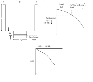
Plate Load Test
- It is conducted to determine ultimate bearing capacity, allowable bearing pressure or probable settlement.
- Plate is usually square sized of side 30 cm (clayey sand soils) to 60 cm (dense sandy and gravel) and thickness of 2.5 cm.
- The test pit width is taken 5 times the width of plate i.e., B = 5 Bp
- A seating load of 7 kN/m2 is applied initially and maximum load that is to be applied is taken 1.5 times the probable ultimate load or 3 times proposed allowable bearing pressure.
- Load increments shall be approximately one-fifth of the estimated safe-bearing pressure calculated.
- Settlements are measured by four independent dial gauges and average value is taken at each increment.
- Load at which the settlement occurs in a rapid rate is taken as ultimate bearing capacity of the soil.
- For each load increment, the settlement value is taken and we draw the Load-settlement curve.
- If yield point is not specific in the graph, load corresponding to settlement equal to one-fifth of wide of plate is taken.
- Since load test is of short duration, settlement due to consolidation cannot be predicted especially in cohesive soil. Settlement of foundation. For clayey soil, Sf/Sp = Bf/Bp
S corresponds to settlement and B for breadth or width f indicates footing and p indicates plate.
For sandy or cohesionless soils, Sf = Sp[Bf(Bp+0.3/Bp(Bf+0.3))]2
Note: All values should be in meters.
Ultimate bearing capacity of foundation
For Clayey Soils, (qu)f = (qu)p
For Sandy Soils, (qu)f /(qu)p = Bf/Bp (Kindly, remember this equations carefully as these are very important for GATE Exam)
EARTH PRESSURE
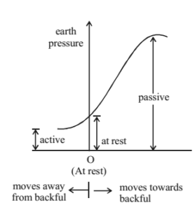
Depending on the lateral pressure exerted by the soil on the retaining structure and based on movement of the retaining structure, there are three types of earth pressures.
Comparison of Earth Pressure at rest, Active Earth Pressure and Passive Earth Pressure
|
Earth Pressure at rest |
Active Earth Pressure |
Passive Earth Pressure |
|
Retaining wall does not move. Elastic Equilibrium Horizontal earth pressure, k0 = µ/1-µ ≈ 1-sinφ where µ is Poisson’s ratio σv = γ.z |
Retaining wall moves away from backfill Plastic equilibrium σh = σ3 σv = σ1 |
Retaining wall moves towards back fill Plastic equilibrium σh = σ1 σv = σ3 |
|
Failure plane inclined at (45+φ/2) to horizontal |
Failure plane inclined at (45-φ/2) to horizontal |
|
|
At plastic equilibrium, σ1 = σ3.tan2(45+φ/2)+2C.tan(45+φ/2) |
||
Active earth pressure has minimum value and passive earth pressure has maximum.
Tip – Either study the properties of active earth pressure or passive earth pressure and note the difference in the other one. It is better not to study both together and confuse values of σh and σv
What is Rankine’s Theory and what does it say?
RANKINE’S THEORY
Assumptions:
- Soil dry, homogeneous, cohesionless, semi-infinite.
- Ground surface is a horizontal or inclined plane.
- Back of retaining wall is smooth and vertical.
- Plastic equilibrium condition.
- Wall yields about the base.
1. Dry cohesion less soil
| Active Pressure | Passive Pressure |
| Active pressure, Pa = Ka.σv σv = rz Ka is coefficient of active earth pressure Ka = 1/tan2(45+φ/2) = tan2(45-φ/2) = 1-sinφ/1+sinφ For cohesive soil, φ=0 => K0 = 1 | Passive pressure, Pp = Kp.σv σv = rz Kp is coefficient of passive earth pressure Kp = 1/tan2(45-φ/2) = tan2(45+φ/2) = 1+sinφ/1-sinφ For cohesive soil, φ=0 => Kp = 1 |
Note:
- Ka = 1/Kp
- When φ = 0, Ka = Kp = 1
- When z = 0, i.e., at top of the wall, Pa = Pp = 0
VARIATION OF LATERAL PRESSURE
Case I – Pressure distribution is triangular.
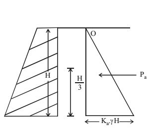
Resultant active earth pressure, Pa = 0.5 x Ka.γ.H x H
Note – Replacing Ka with Kp gives the passive earth pressure. The resultant is acting horizontally at height of H/3 from bottom.
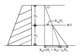
Case II – Water table at the top of the retaining wall.
Pressure at any depth, Pa = Ka.γZ + γwZ
Case III – Water table between top and base of retaining wall.
If water is there on both sides of retaining wall, the effect of water need not be considered. Take Pa as in case I
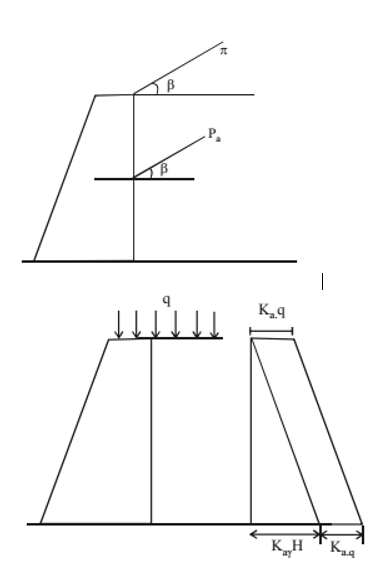
Case IV – Inclined ground surface
Ground surface is inclined E with horizontal.
The resultant Pa will be inclined at the same angle β at height of H/3 from horizontal.
Case V – Backfill with uniform surcharge
At any depth,
Pa = Ka.γ.Z + Ka.q
At top (H=0) Pa = Kaq.q
At bottom (H=Z) Pa = KaγH + Kaq
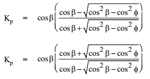
Note – There is no change in sign inside the root. There is square for cos b and cos f only inside the root.
GEOTECHNICAL ENGINEERING ACE GATE MATERIAL : CLICK HERE
2. Cohesive Backfill
Active Pressure Pa = Kaσv – 2C√Ka = Kaγz– 2C√Ka
When Z=0, i.e., at top Pa = -2C√Ka
When Z=H at bottom, Pa = KaγH – 2C√Ka
There is a point where tension becomes zero, it is called Tension Crack.
Depth of tension crack Zc = 2Ctanα/γ = 2C/γ√Ka where Ka = 1/tan2α and α = 45+φ/2
Total Active Force
Before formation of tension crack, Pa = KaγH2/2 – 2C√Ka.H
After formation of tension crack, Pa = KaγH2/2 – 2C√Ka.H + 2C2/r
This acts at a height of one-third from base of bottom triangle, i.e. (H-Zc)/3 from bottom (Height of lower triangle = H-Zc)
Passive Pressure
PP = Kp.σv + 2C√Kp
Total passive force = KpγH2/2 + 2C√Kp.H
Critical Height (Hc)
It is the depth upto which vertical excavation can be done on cohesive soil without any lateral support.
Hc = 2Zc = 4C/γ√Ka = 4C/γ x tan2α (α = 45+φ/2)
For pure cohesive soil (clay), φ=0 => Hc = 4C/γ
Note
- There is no tension formation in case of passive pressure as value of Pp is always positive for any value of Z.
- Effect of cohesion is to reduce active pressure by a 2C√Ka and increase passive pressure by 2C√Kp
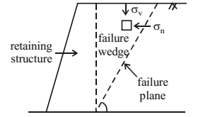
What is Coulomb’s Thery and what does it say?
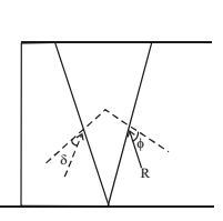
COULOMB’S THEORY
The main difference between Rankine’s theory and coulomb’s wedge theory is that here the wall surface is assumed to be rough.
The inclination of resultant earth pressure to normal to the wall is taken as δ. It is the angle of friction between wall and the backfill.
For smooth walls, Angle of friction δ = φ/3
For concrete walls, Angle of friction δ = 2φ/3
For rough walls, Angle of friction δ = 3φ/4
For backfill subject to vibration, Angle of friction δ = 0
STABILITY OF SLOPES
Types of Slopes:
- Infinite slope: slopes of greater extend having soil properties and soil compression constant for all identical depths below the top surface.
- Finite slope: slopes having limited length like in earth dams, highway cuts, railway cuts etc.
Types of Slope Failures
- Translational failure – Failure of slope occurs parallel to the slope at some depth below it. It is common in case of infinite slope.
- Rotational failure – Failure surface is curved and is caused by rotation.
Stability of Infinite Slope
- Infinite slope in C – φ Soil
Factor of Safety = Shear Strength/Shear Stress
- Fc = S/τ
- Fc = C+γZcos2i.tanφ)/γZcos(i).sin(i)
Where φ is angle of internal friction, i = angle of infinite slope
- Infinite slope in dry sand
For dry sand, C = 0
Therefore, F = (0 + γZcos2i.tanφ)/ γZcos(i).sin(i) = tanφ/tan(i)
Stability Number (Sn)
Used forC – φ Soil, it is dimensionless quantity.
Sn = C/FcγH = Cm/γH = C/γHc x (tani – tanφ)cos2i
Reciprocal of stability number is called stability factor
Note
- If the slope angle i is less than or equal to angle of internal friction φ, the slope is stable.
- If i > φ , slope can be stable only upto a certain height called critical height (Hc)
Hc = C/r(tan i – tan φ)cos2C
- Also, Hc = H x Fc where H is actual height of slope
- Mobilised cohesion (Cm) is cohesion of soil when factor of safety (Fc) is applied.
Cm = C/Fc => Fc = C/Cm => Fc = Hc/H = C/Cm

- For pure cohesion less soil, C=0 and Sn = 0
- Maximum value of Sn = 0.261
- For fully submerged soil, Fs = rsub/rsat x tanφ/tanβ, S = C/Fcγ’H (γ’= γsub)
- For slope saturated by capillary water, Sn = C/FcγsatH
Stability of Finite Slope:
Types of failure in finite slope
- Face failure
- Toe failure
- Base failure
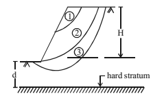
- Failure of finite slope is due to rotational failure.
- Factor of safety against rotational failure.
F = Resisting moment/Driving moment
Depth Factor (Df)
Df = H+d/H = depth of hard stratum from top of slope/depth of slope
When,
Df < 1, face failure (hard stratum inside slope)
Df = 1, toe failure (i.e., d = 0)
Df > 1, base failure (hard stratum below base of slope)
Methods of stability analysis of finite slope
- φu = 0 analysis (for purely cohesive soil)
- C – φ analysis (for cohesive soil)
- Slip circle method.
- Friction circle method.
- Stability number method.
- Bishop’s method
FOUNDATION
TYPES OF FOUNDATION
1. Based on depth
Shallow foundation – If the depth or width of the footing is less than or equal to its breadth, it is called shallow foundation. Failure is usually rotational bearing failure. Example – spread footing, Raft or mat footing.
Deep foundation – If the depth of footing is more than its breadth, it is called deep foundation. Example – Pile foundation D > B
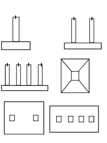
2. Based on its structure
Isolated footing – It is constructed under base of the wall or below a column.
Combined footing – Two or more footing joined together. Used if the base of footing overlap or is very close to each other.
Strip footing – Length of foundation is much more than its width.
Mat or raft foundation – The whole footing or column is on a single layer of foundation.
Pile foundation – Piles are inserted into the soil where there is no hard stratum near the surface.
(a) End bearing pile – The pile which directly transmits the load to the hard stratum at a greater depth.
(b) Friction pile – Pile which carry the load by friction b/w surface of pile and surrounding soil.
(c) Compaction pile – Piles which are inserted into cohesion-less soil to increase shear strength of soil. Example – Sand pile.
3. Based on Material
- Concrete foundation
- Steel foundation
- Wooden foundation
- Bamboo foundation
- Sand pile
- Brick foundation
Foundation design requirement
Foundation is designed to satisfy two main requirements
- No shear failure
- No excessive settlement
IES MASTER SOIL MECHANICS GATE STUDY MATERIAL : CLICK HERE
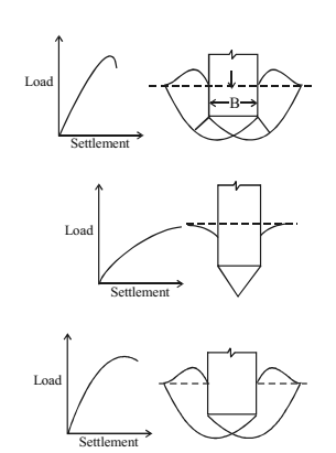
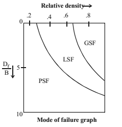
SHEAR FAILURE
TYPES OF SHEAR FAILURE
- General shear failure (GSF)
– failure is well defined
– occurs in dense soils
– heave on both sides
- Punching shear failure (PSF)
– no well defined slip line
– No heaving
– occurs in loose sand
- Local shear failure (LSF)
– characteristics of both GSF and PSF
– Shows vertical shear and slight building
– Slight bulging/ heaving
– Occurs in cohesive soil for shear strength Cu < 50 kN/m2
Criteria for GSF and LSF
| Criteria | GSF | LSF |
| Φ | > 360 | < 280 |
| Relative Density | > 70% | < 20% |
| N | > 30 | < 5 |
| e | < 0.55 | > 0.75 |
| Failure Strains | < 5% | 10 – 20% |
Excessive settlement
– Allowable settlement depends on type of soil and foundation
– Allowable settlements
| Foundation → Soil ↓ | Isolated Footing | Raft Footing |
| Sand, hard clay, (cohesion less soil) | 50 mm | 75 mm |
| Plastic clay (cohesive soil) | 75 mm | 100 mm |
Total settlement
Total settlement = immediate settlement + consolidation settlements Immediate settlements Si, occurs in highly permeable soils
Si = qB(1-µ2/Es)I
Where,
q – Net intensity of contact pressure (kN/m2)
B – Least lateral dimension of footing or loaded area (m)
Es – Modulus of elasticity (kN/m2)
I – Influence factor
µ – Poisson’s ratio value of influence factor depends on the type, shape and rigidity of the footing. (The value will be given in the question paper itself during the exam). The value ranges from 0.8 to 1.7.
Consolidated Settlement (Sc)
Sc = C x Ci/1+C0 x H log (σ0+Δσ/σ0)
Where,
C – Correction factor
H – thickness of compressible layer
Ci – Compression index
σo – effective overburden pressure
eo – initial void ratio
Δσ – vertical stress on footing
Bearing capacity of Soil
Various terms to express the bearing capacity/ bearing pressure of soil.
Gross pressure (q)
Total bearing pressure at the base of the footing due to weight of the structure, self weight of footing and earth fill. In some cases earth fill is not provided. Then take that load as zero.
Net pressure (qn)
It is the pressure in excess of that which existed before construction
qn = Gross pressure – Original overburden pressure that acted on the unit area = q – γD
where, γ = unit weight of soil, D = depth of foundation
Ultimate bearing capacity (qu) – Maximum gross pressure that the soil can withstand before it fails in shear
Net ultimate bearing capacity (qnu)
Maximum net intensity of press. the soil can bear before it fails in shear
qnu = qn – γD
Net safe bearing capacity (qns)
Net safe pressure that the soil can safely withstand without any risk of shear failure
qns = qnu/F
where F – factor of safety, usually taken between 2.5 and 3.
Gross safe bearing capacity (qgs) It is the maximum gross bearing pressure the soil can withstand without shear failure.
qgs = qns + γD = qnu +γD
Net safe settlement pressure (qnp)
It is the maximum net intensity of loading that can be allowed on the soil without the settlement of soil exceeding the permissible value
Net allowable bearing pressure (qna)
It is the maximum net intensity of pressure that can be imposed on soil with no risk of shear failure as well as possibility of excessive settlement. This value is used to design foundation.
qna = qns or qnp whichever is less
Area of foundation
Design criteria for design of foundation
qn ≤ qna
Q/A ≤ qna (back filled)
Q/A – γD ≤ qna (no backfill)
In case of no back fill, Q/A ≤ γD + qna
It is clear that in case of no backfill, bearing capacity is considerably enhanced.
If Q/A = γD, then qna = 0 This is the principle of floating raft foundation where the pressure due to superstructure is equal to overburden pressure, thereby reducing net pressure to zero
Rankine’s Analysis for minimum depth of foundation Depth of foundation,
D = q/γ x [1-sinφ/1+sinφ]2
Where φ – effective angle of shearing, q – intensity of loading, γ – density of soil solids
Terzaghi’s bearing capacity theory
Assumptions
- Footing is shallow (Df < B), continuous
- Base of footing is rough
- GSF occurs
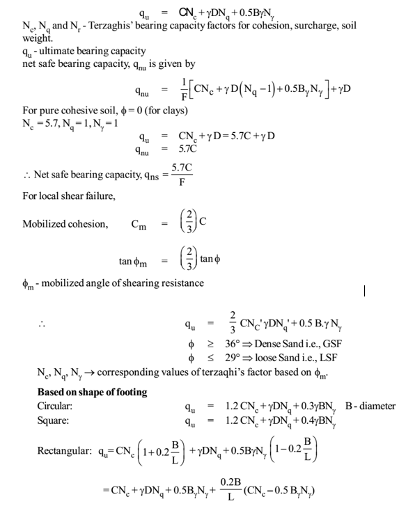
Effect of water table on bearing capacity
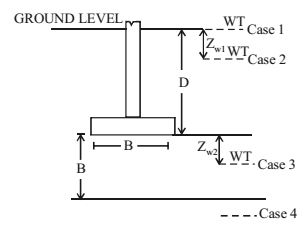
Case 1: Water table (WT) is at or above ground level
use r’ instead of r in the equation.
qu = CNc + γDNq + 0.5Bγ’Nγ
Case 2: When WT is above base of the footing
qu = CNc + γDNqRW1 + 0.5BγNγ
RW1 = 0.5[1 + Zw2/D]
Where Zw1 = Depth of WT below ground level
and Zw2 = Depth of WT below base of the footing, B.
Case 3: WT is below base of footing at depth less than width of footing, B
qu = CNc + γDNq + 0.5BγNγ.Rwz
Rw2 = 0.5[1 + Zw2/B]
Zw2 = Depth of the WT below base of the footing, B.
Case 4: WT below base of footing, at depth more than width of footing, B.
NO Correction is required in this case.
Points to be noted:
- Value of Rw1 and Rw2 ranges from 0.5 (where Zw1 or Zw = 0) to 1 (where Zw1 or Zw = 1)
- Note that in equation of Rw1 it is Zw1 divided by D and for Rw2 it is Rw2 divided by B.
GEOTECHNICAL ENGINEERING ACE GATE NOTES : CLICK HERE
Correction of Bearing Capacity
Clayey Soils –
Size of footing or plate does not affect the bearing capacity. The bearing capacity found out during plate load test is taken for the design of foundation in clayey soil.
qp ≈ qf
Sandy Soils –
Bearing capacity is directly proportional to width or side of the footing/plate
q α B where qf is Bearing capacity of footing
qf/qp = Bf/Bp where qp is Bearing capacity of plate in plate load test
Skempton’s Method
Skempton’s method is applicable only to cohesive soil.
Bearing capacity factor Nc increases with ratio Df/B
Strip footing
When D = 0, Nc = 5.14 (On Surface). This is the minimum value
When D/B < 2.5, Nc = 5 [1 + 0.2D/B] = 5 + D/B
When D/B > 2.5, Nc = 5 x 1.5 = 7.5, this is the maximum value
Rectangular Footing
Nc = 5[1 + 0.2D/B][1 + 0.2B/L]
Minimum value of Nc is 6.2 and maximum value is 9
PILE FOUNDATION
Classification of Piles
Based on load transfer
- End bearing pile – The load of the superstructure (Qu) is transferred to the hard strata through the pile tips (Qb)
- Friction pile or floating pile – Load is transferred by skin friction between soil and surfaced pile used when hard strata is not available at reasonable depth.
- Combined end bearing and friction pile – Load transferred by combination of end bearing and friction force.
Based on function
- Compaction pile – For compaction of loose granular soil and to increase the bearing capacity. Eg: Sand piles
- Tension piles – To anchor down structures which are subjected to uplift force.
- Anchor piles – To provide anchorage against horizontal pull from sheet pile walls.
- Fender piles and dolphins – They are sheet piles used to protect water front structures against impact from ships and other floating bodies.
- Batter piles – These piles are provided to resist lateral or inclined forces due to moving or berthing of ships.
Based on method of installation
- Driven cast-in- situ piles – The casing is driven and pile is cast-in-situ.
- Precast driven piles – Pile is precast and is driven into soil
- Bored cast-in-situ – Bores are made on the ground and piles are cast in situ.
Based on material of pile
- Conevete pile
- Jimber pile
- Steel pile
- Composite pile
Points to be noted
- All driven piles comes under displacement piles i.e., they cause lateral displacement of soil when installed.
- All bored piles are non displacement piles
LOAD CARRYING CAPACITY OF PILE
STATIC FORMULAE
This formula is based on strength properties of soil. The load transferred by a pile is equal to sum of that transferred by end bearing and skin friction.
Ultimate load capacity of pile,
Qu = Qb + Qs
Where,
Qb = end bearing resistance/ capacity
Qs = skin friction capacity or side friction capacity
Qb = Abfb
Qs = Asfs
Where
Ab = base section area of pile
As = Surface area of pile (2πr.D)
fb, fs = bearing capacity and skin friction of pile
Load Capacity of pile in sand
Qu = Qb + Qs = Abfb + Asfs
For piles in sand,
fb = σv’.Nq , where Nq = bearing capacity factor
σv’ = γ’L if L<Dc where L = Length of pile
σv’ = γ’Dc if L≥Dc where Dc = Critical depth
i.e., σv’ = γ’.(L or Dc whichever is lesser)
Dc = 10xd for loose sand where d=diameter of pile
= 20xd
fs = K.σa’.tanδ
K = Lateral earth pressure coefficient
σa’ = Average vertical pressure for the depth
δ = Angled friction between pile and soil
Therefore, Qu = AbσV’Nq = As.k. σa’.tanδ
Load Capacity of pile in clay
Qu = Abfb + Asfs
fb = CNc
where C = Cohesion of soil at pile tip = shear strength of soil at pile tip, Nc=9
fs = αC where α = Shear mobilization factor or adhesion factor
Qu = Ab.C.Nc + As.α.C
Safe load capacity of pile = Qu/F
Factor of Safety, F = 2.5 for static formulae
Group action of piles
Efficient of group pile, ηg = Qgx100/n.Qu
ηg can be greater than or less than 100%. It is usually greater than 100% for loose and medium dense sands and less than 100% for dense sands.
Spacing of Piles in group pile
For end bearing piles, spacing = 2.5.d where d = diameter of pile.
For friction piles, spacing = 3 × d
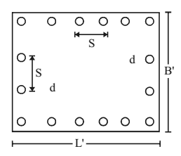
Failure of group pile
a. Individual failure
Group capacity of pile group, Qg = n x Qu
Where n is number of piles, Qu is ultimate load capacity of each pile
b. Block failure
Group capacity, QB = ABfB + Asfs
AB = L’ x B’
As = 2(L’ + B’) x L
L’ = (n-1)s + d
Where n is number of piles on that side, d is diameter of pile, L is length of pile
Note : Group capacity for calculations is taken the smaller value from these values of group capacity.
DYNAMIC FORMULAE
This formula is based on energy input to drive the pile.
Engineering news formulae : Qs = Whηh/F(S+C)
Where
W – Weight of hammer in kg.
h – height of drop
ηh – efficiency of pile hammer (Usually taken as 1)
F – factor of safety (usually 6)
S – penetration of pile/ hammer blow
C ≈ 2.5 (C=2.4 for drop hammer and 2.53 for singe and double acting hammers)
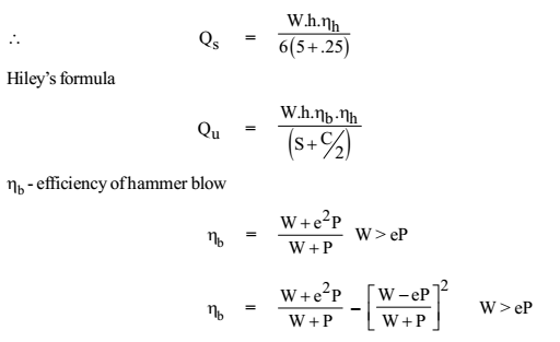
Where
P = weight of pile
e = coefficient of restitution
e = 0 for timber pile, e = 0.5 for RCC and steel pile
Note: This equation is applicable only to friction pile.
For end bearing P is reduced to half.
Where C = effective elastic compression = sum of temporary elastic compression of dolly and pecking, pile and ground = C1 + C2 + C3
Point to remember – Dynamic formula is test suited for coarse grained soil and not for deep and silt underwater.
Pile Load Test
- Used to determine capacity of individual pile.
- Maximum load on the pile should not be less than 2.5 times estimated load and for working pile it should not be less than 1.5 times.
- The load settlement curve is drawn, and least of the following is taken as safe load
- 2/3rd of final load which given total settlement 12 mm.
- 2/3rd load which gives net settlement of 6 mm.
- 1/2 of load at which total settlement is 1/10 of pile diameter.
Negative Skin Friction (Downward drag)
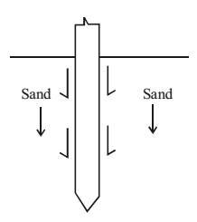
When soil around the pile settles in a faster rate than the pile, a downward skin friction between soil and pile is developed.
This is called ‘negative skin friction’. This occurs when pile is drives through soil before consolidation is complete or when water take is covered.
Negative skin friction causes reduction in load carrying capacity of pile.
Negative skin friction, Qn = πd.L.C
Where d – diameter of pile, πd.L – surface area of pile, C – cohesion
Therefore, Qn = πd.L.K.σa’.Tanδ
FOUNDATION ENGINEERING CIVILENGGFORALL EXCLUSIVE GATE PSU ESE MATERIAL IN PDF FORMAT : CLICK HERE
PASSWORD : CivilEnggForAll
OTHER USEFUL POSTS
- RAJASTHAN STAFF SELECTION BOARD (RSSB) JUNIOR ENGINEER DIPLOMA CIVIL ENGINEERING EXAM 2022 – HINDI & ENGLISH MEDIUM SOLVED PAPER – FREE DOWNLOAD PDF (CivilEnggForAll.com)
- ISRO TECHNICAL ASSISTANT EXAM 2022 – CIVIL ENGINEERING – HINDI & ENGLISH MEDIUM – SOLVED PAPER – FREE DOWNLOAD PDF (CivilEnggForAll.com)
- MADHYA PRADESH PUBLIC SERVICE (MPPSC) COMMISSION – ASSISTANT ENGINEER EXAM – MPPSC AE 2021 CIVIL ENGINEERING – SOLVED PAPER WITH EXPLANATIONS – PDF FREE DOWNLOAD
- BIHAR PUBLIC SERVICE COMMISSION (BPSC) ASSISTANT ENGINEER EXAM – 2022 – CIVIL ENGINEERING – SOLVED PAPER – FREE DOWNLOAD PDF (CivilEnggForAll.com)
- ODISHA PUBLIC SERVICE COMMISSION – OPSC AEE PANCHAYATI RAJ EXAM 2021 – SOLVED PAPER WITH EXPLANATION – FREE DOWNLOAD PDF